
USER
MANUAL
QuantusSoftware provides a quick and user-friendly way to interact with QuantusSeries hardware. It is accomplished by providing a REST interface available on the hardware. The REST interface uses HTTP and JSON requests.
The key benefits of a REST interface are:
The current release of QuantusSoftware is Q 2.5.1.
Q2.4.16 to Q 2.5.1
Q2.4.15 to Q2.4.16
Q2.4.12 to Q2.4.15
Q2.4.11 to Q2.4.12
Q2.4.10 to Q2.4.11
Q2.4.8 to 2.4.10
Q2.4.6 to Q2.4.8
Q2.4.4 to Q2.4.6
Q2.4.3 to Q2.4.4
Q2.4.2 to Q2.4.3
Q2.3.4 to Q2.4.2
Q2.3.3 to Q2.3.4
Q2.3.2 to Q2.3.3
Q2.3.1 to Q2.3.2
Q2.3.0 to Q2.3.1
Q2.2.3 to Q2.3.0
/?embedded is 315 pixels and with vertical split /?embedded&verticalSplit is 632 pixels.Q2.2.2 to Q2.2.3
Q2.2.1 to Q2.2.2
Q2.2.0 to Q2.2.1
Q2.1.1 to Q2.2.0
?embedded to the QAcquire link in the browser. The complete URL should be http://<Device>/QAcquire/?embedded&verticalSplit after ?embedded in the QAcquire link. The complete URL should be http://<Device>/QAcquire/?embedded&verticalSplitQ2.1.0 to Q2.1.1
Q2.0.306 to Q2.1.0
Q2.0.298 to Q2.0.306
Q2.0.264 to Q2.0.298
Q1.4.11 to Q2.0.264
Q1.4.6 to Q1.4.11
Q1.4.5 to Q1.4.6
Q1.4.3 to Q1.4.5
Q1.4.2 to Q1.4.3
Q1.4.1 to Q1.4.2
Q1.3.3 to 1.4.1
Q1.2.416 to Q1.3.3
Q1.2.413 to Q1.2.416
Q1.2.412 to Q1.2.413
QuantusSoftware version Q2.0 introduces many breaking changes. These changes were needed due to added features and customer feedback. This section will guide developers that are migrating from Q1.X to Q2.X.
Multiple endpoints were renamed to improve readability, extendability and ease of integration.
See the list below for all the Endpoint changes:
| Action | Original Endpoint | New Endpoint |
|---|---|---|
| GET | systemSettings | system/settings |
| PUT | systemSettingsApply | system/settings/apply |
| PUT | resetSystemToDefaults | system/settings/resetToDefaults |
| GET | operationMode | item/operationMode |
| PUT | operationMode | item/operationMode |
| GET | itemSettings | item/settings |
| PUT | itemSettings | item/settings |
| GET | itemDefaultSettings | item/settings/defaults |
| GET | itemList | item/list |
| PUT | subscribeToData | This endpoint has been removed |
| GET | unsubscribeFromData | This endpoint has been removed |
| GET | autoZero | autoZero/settings |
| PUT | autoZero | autoZero/settings |
| PUT | autoZero | autoZero/settings/apply |
| PUT | aloFaultCondition | alo/faultCondition |
| GET | canMessageList | canfd/message/list |
| PUT | canMessageList | canfd/message/list |
| DELETE | clearCanMessageList | canfd/message/list |
| PUT | transmitCanFdMessage | canfd/message/transmit |
| PUT | abortCanFdTransmission | canfd/message/abortTransmission |
| GET | canFdBusStatus | canfd/bus/status/list |
| GET | dataStreamingSetup | dataStream/setup |
| PUT | suspendDataStream | dataStream/suspend |
| PUT | resumeDataStream | dataStream/resume |
| PUT | doBridgeBalance | wsb/bridgeBalance/apply |
| PUT | clearBridgeBalance | wsb/bridgeBalance/reset |
This Q 2.0 release strives to standardize the RESTfull response from the endpoint calls.
For all Settings, MessageData and CanFdBusStatus objects, the Type field responses has been update for the following values:
| Original Type Value | New Type Value |
|---|---|
| unsigned char | Byte |
| unsigned char [] | Byte [] |
Some endpoint responses were to be changed, they are listed below:
 {
    "System": {
        "ItemId": 1,
        "ItemName": "PQ30G2",
        "ItemNameIdentifier": 30090,
        "ItemType": "Controller",
        "ItemTypeIdentifier": 0,
        "Info": [
            {
                "Name": "SerialNumber",
                "Value": "1118M3103"
            }
        ],
        "OperationMode": {
            "Description": "Enabled",
            "Value": 1
        },
        "SettingsApplied": true,
        "Settings": [
... {
"ItemId": 1,
"ItemName": "PQ30G2",
"ItemNameIdentifier": 30090,
"ItemType": "Controller",
"ItemTypeIdentifier": 0,
"Info": [
{
"Name": "SerialNumber",
"Value": "1118M3103"
}
],
"OperationMode": {
"Description": "Enabled",
"Id": 1
},
"SettingsApplied": true,
"Settings": [
... {
"ItemId": 1,
"ItemName": "PQ30G2",
"ItemNameIdentifier": 30090,
"ItemType": "Controller",
"ItemTypeIdentifier": 0,
"Info": [
{
"Name": "SerialNumber",
"Value": "1118M3103"
}
],
"OperationMode": {
"Description": "Enabled",
"Value": 1
},
"SettingsApplied": true,
"Settings": [
...{
"ItemId": 1,
"ItemName": "PQ30G2",
"ItemNameIdentifier": 30090,
"ItemType": "Controller",
"ItemTypeIdentifier": 0,
"Info": [
{
"Name": "SerialNumber",
"Value": "1118M3103"
}
],
"OperationMode": {
"Description": "Enabled",
"Id": 1
},
"SettingsApplied": true,
"Settings": [
...{
"ItemId": 7,
"ItemName": "ICS425",
"ItemNameIdentifier": 15,
"ItemType": "Channel",
"ItemTypeIdentifier": 4,
"AutoZeroSettings": [
...{
"ItemId": 7,
"ItemName": "ICS425",
"ItemNameIdentifier": 15,
"ItemType": "Channel",
"ItemTypeIdentifier": 4,
"Settings": [
...{
"MessageList": [
[
{
"Name": "Extended Frame",
"Type": "Enumeration",
"SupportedValues": [
{
"Id": 0,
"Description": "Disabled"
},
{
"Id": 1,
"Description": "Enabled"
}
],
"Value": 1
},
...[
{
"Settings": [
{
"Name": "Extended Frame",
"Type": "Enumeration",
"SupportedValues": [
{
"Id": 0,
"Description": "Disabled"
},
{
"Id": 1,
"Description": "Enabled"
}
],
"Value": 1
},
{
"Name": "Message ID",
"Type": "Unsigned Integer",
"ValidationLimits": {
"Upper": 4294967295,
"Lower": 0
},
"Value": 4
},
{
"Name": "Message Length",
"Type": "Unsigned Integer",
"ValidationLimits": {
"Upper": 64,
"Lower": 0
},
"Value": 64
},
{
"Name": "Transmit Period In Milliseconds",
"Type": "Unsigned Integer",
"ValidationLimits": {
"Upper": 4294967295,
"Lower": 0
},
"Value": 0
},
{
"Name": "Hold Period In Milliseconds",
"Type": "Unsigned Integer",
"ValidationLimits": {
"Upper": 4294967295,
"Lower": 0
},
"Value": 0
}
],
"MessageData": {
"Name": "Message Data",
"Type": "Byte []",
"ValidationLimits": {
"Upper": 255,
"Lower": 0
},
"Value": [
1,
2,
3,
4,
...{
"Bus Status": [
{
"Name": "Transmit Error Count",
"Type": "Unsigned Integer",
"ValidationLimits": {
"Upper": 4294967295,
"Lower": 0
},
"Value": 0
},
{
"Name": "Receive Error Count",
"Type": "Unsigned Integer",
"ValidationLimits": {
"Upper": 4294967295,
"Lower": 0
},
"Value": 0
},
...[
{
"Name": "Transmit Error Count",
"Type": "Unsigned Integer",
"ValidationLimits": {
"Upper": 4294967295,
"Lower": 0
},
"Value": 0
},
{
"Name": "Receive Error Count",
"Type": "Unsigned Integer",
"ValidationLimits": {
"Upper": 4294967295,
"Lower": 0
},
"Value": 0
},
...There has been a change in how users enable/disable data streaming for channels.
In Q1.X, data streaming was enabled using the /subscribeToData endpoint. In Q2.X, there is now a setting on the channel to enable/disable streaming. This is the same mechanism to enable Local Storage for the selected channel. To enable data streaming for a channel, the Streaming State setting should be set to Enabled (Id: 1), which will require a system/settings/apply before the change takes effect.
The settings for a channel will now have the additional section:
"Data":[
        {
            "Name":"Streaming State",
            "Type":"Enumeration",
            "SupportedValues":[
                {
                    "Id":0,
                    "Description":"Disabled"
                },
                {
                    "Id":1,
                    "Description":"Enabled"
                }
            ],
            "Value":1
        },
        {
            "Name":"Local Storage State",
            "Type":"Enumeration",
            "SupportedValues":[
                {
                    "Id":0,
                    "Description":"Disabled"
                },
                {
                    "Id":1,
                    "Description":"Enabled"
                }
            ],
            "Value":1
        }
]Some settings and Operation Mode names have been renamed for consistency:
| Item | Setting Group | Original Value | New Value |
|---|---|---|---|
| All items with children | SubNodes field | SubNodes | Children |
| All items with settings | SettingsApplied | Text as “True” or “False” | Boolean |
| ICT42S6 Scope Channel | Operation Mode | Scope Enabled | Enabled |
| ICT42S6 Tacho Channel | Operation Mode | Tacho Enabled | Enabled |
| ICT426 Scope Channel | Operation Mode | Scope Enabled | Enabled |
| ICT426 Tacho Channel | Operation Mode | Tacho Enabled | Enabled |
| TAC221 Scope Channel | Operation Mode | Scope Enabled | Enabled |
| TAC221 Tacho Channel | Operation Mode | Tacho Enabled | Enabled |
| XMC100 Module | Settings | Sample Rate | ICP Channel Sample Rate |
| XMC237 Module | Settings | Sample Rate | ICP Channel Sample Rate |
| CAN42S2 Channel | Settings | Fast Bitrate | Send At Fast Bitrate |
Some settings were previously hidden and are now exposed. The majority of these will only have one option. The change is to give the user more information about the configuration of the item. These changes are not breaking changes, but will change the way GUI’s might automatically populate fields for channel settings.
| Item | Operation Mode | Setting Name |
|---|---|---|
| CHS42X4 Channel | Charge Input | Input Coupling |
| CHS42X4 Channel | Icp Input | Current Source |
| ICP4211 Channel | Icp Input | Current Source |
| ICP4211 Channel | Icp Input | Input Biasing |
| ICP42S11 Channel | Icp Input | Input Biasing |
| ICS421 Channel | Icp Input | Current Source |
| ICS425 Channel | Icp Input | Current Source |
| ICT426 Icp Channel | Icp Input | Current Source |
| ICT426 Icp Channel | Icp Input | Input Biasing |
| ICT42S6 Icp Channel | Icp Input | Input Biasing |
| MIC42X7 Channel | Icp Input | Input Biasing |
| MIC42X7 Channel | Microphone Input | Preamp Excitation |
| THM427 Channel | Thermocouple Input (all types) | Voltage Range |
| THM427 Channel | Pt100 Input | Voltage Range |
| XMC237 Icp Channel | Icp Input | Input Biasing |
| XMC237 Icp Channel | Icp Input | Coupling |
In the Packet Header, the Reserved field has been replaced by Payload Type. This new Payload Type allows QServer to add metadata into the data stream. Q1.X only implemented streaming data payloads, which is now indicated as Payload Type equal to 0.
Note: Initially, when migrating from Q1.X to Q2.X, the software receiving the data stream should check the Payload Type and ignore all types that are not Data (0), and treat Data types the same way as Q1.X. Once the migration of the Packet Header* and Generic Channel Header has been completed, users can incorporate other Payload Types.
The Packet Header layout change is as follows:
| Original | New |
|---|---|
| (64-bit unsigned integer) Sequence number (64-bit floating point) Timestamp (32-bit floating point) Buffer level (32-bit unsigned integer) Payload size (32-bit unsigned integer) Byte order marker (32-bit unsigned integer) Reserved |
(64-bit unsigned integer) Sequence number (64-bit floating point) Transmit Timestamp (32-bit floating point) Buffer level (32-bit unsigned integer) Payload size (32-bit unsigned integer) Byte order marker (32-bit unsigned integer) Payload type |
Introducing IEEE 1588-2008 PTP required the addition of a timestamp in the Generic Channel Header. There has also been a minor improvement to make implementing data streamers easier by changing the Offset To Next Header to Data Size.
The Generic Channel Header changes are as follows:
| Original | New |
|---|---|
| Generic Channel Header (32-bit signed integer) Channel Id (32-bit signed integer) Channel Type (32-bit unsigned integer) Sample Type (32-bit unsigned integer) Offset To Next Header |
Generic Channel Header (32-bit signed integer) Channel Id (32-bit signed integer) Channel Type (32-bit unsigned integer) Sample Type (32-bit unsigned integer) Data Size (64-bit unsigned integer) Timestamp |
| Analog Channel Header (32-bit unsigned integer) Size DataStats Stats |
Analog Channel Header (32-bit signed integer) Channel Integrity (32-bit signed integer) Overload has occurred (32-bit floating point) Level (32-bit floating point) Min (32-bit floating point) Max |
| Tacho Channel Header (32-bit unsigned integer) Size (32-bit unsigned integer) Reserved |
Removed |
| CanFD Channel Header (32-bit unsigned integer) Size (32-bit unsigned integer) Reserved |
CanFD Channel Header (32-bit unsigned integer) Reserved (32-bit unsigned integer) Reserved (32-bit unsigned integer) Reserved (32-bit unsigned integer) Reserved (32-bit unsigned integer) Reserved (32-bit unsigned integer) Reserved |
| GPS Channel Header (32-bit unsigned integer) Size (32-bit unsigned integer) Reserved |
Removed |
Note: The fields in the data payloads are packed tightly without any padding. They should be parsed on a byte-for-byte basis.
Each sample type is now unique for its matching channel type
| Channel Type | Sample Type |
|---|---|
| Analog | 0 : 32-bit floating point |
| Tacho | 0 : 64-bit floating point |
| CAN FD | 0 : Byte |
| Issue | Workaround |
|---|---|
| Unable to update/clear individual CAN FD messages in the message list. | Please use the canMessageList action to update the whole list. |
| Using the ICT42S6 module in conjunction with the TAC221 on their maximum data rates causes a buffer overflow resulting in QServer becoming unresponsive. | Avoid using the ICT42S6 or ICT426 in a MicroQ. |
| Upgrading QSoftware is noticeably slower when the system is configured with higher data rates. | None. |
| The Overload Occurred field, which has been renamed to Level Crossing Occurred, has become unsupported. | Use the Channel Integrity field to detect an input overload instead. |
| MicroQ built-in ICP channels do not work if one of the channels are disabled. | Either enable or disable both channels |
| ALO42S4 Mirror Mode does not support sampling rates lower than 1024. | Select a higher sampling rate than 1024 |
| ALO42S4 Mirror Mode has an invalid scaling when the ICP42S11 is used with a 60 V input range. | Avoid using the 60 V range on ICP42S11 together with ALO42S4 Mirror Mode. |
QuantusSoftware supports the following features:
| Feature | Supported |
|---|---|
| REST JSON interface | √ |
| mDNS for easy device discovery | √ |
| Number of streaming clients allowed | 1 |
| Local Storage | √ |
| IEEE 1588-2008 PTP synchronization | √ |
| GPS synchronization | X |
Limitations regarding streaming:
Limitations regarding Local Storage:
| Feature | Supported |
|---|---|
| ICP4211 | √ |
| ICP42S11 | √ |
| ICS425 | √ |
| ICT42S6 ICP | √ |
| ICT426 ICP | √ |
| WSB42X2 | √ |
| WSB42X5 | √ |
| WSB42X6 | √ |
| CHG42S9 | √ |
| CHS42X4 | √ |
| DCH42S2 | √ |
| THM427 | √ |
| ICS42L5 | √ |
| MIC42X7 | √ |
| ICT42S6 Tacho | √ |
| ICT42S6 Scope | X |
| ICT426 Tacho | √ |
| ICT426 Scope | X |
| TAC221 Tacho | √ |
| ALO42S4 | X |
| XMC237 CAN FD | X |
| XMC237 ICP | X |
| XMC237 GPS | X |
| ALO450 | X |
| CAN450 | X |
| GPS42S6 | X |
| GPS450 | X |
| ICM450 | √ |
| ICP450 | √ |
| ICS450 | √ |
| ICT454 | √ |
| MIC450 | √ |
| THM450 | √ |
| VIM450 | √ |
This section contains a summary of the hardware supported in QServer and QAcquire. Please see the relevant hardware manuals and brochures for a detailed explanation about the features and hardware capabilities, not yet supported by QServer.
| Controller |
|---|
| PQ10: MicroQ |
| PQ45 |
| Feature | QServer | QAcquire |
|---|---|---|
| All modes | ||
| Grounding | √ | √ |
| Device Under Control input | X | X |
| Module Status output | √ | √ |
| 5 V / 12 V output | √ | √ |
| Function Generator mode | ||
| Basic functions | √ | √ |
| Arbitrary waveforms | √ | X |
| Fade output in/out, smooth transitions | √ | √ |
| User Data mode | ||
| Streaming data | √ | X |
| Change sample rate | √ | √ |
| Feature | QServer | QAcquire |
|---|---|---|
| Streaming data | √ | X |
| Listen-only and Participate mode | √ | √ |
| Selectable bitrates (Arbitration and Data) | √ | √ |
| Messages can be sent individually | √ | X |
| Messages can be scheduled to be sent periodically | √ | X |
| Bus faults can be queried for diagnostic purposes | √ | √ |
| Remote transmission request frames | X | X |
| CAN42S and CAN450 only | ||
| On-board selectable bus termination per channel | √ | √ |
| Feature | QServer | QAcquire |
|---|---|---|
| All modes | ||
| Streaming data | √ | √ |
| Data level, min and max | √ | X |
| Autozero | √ | √ |
| Integrity monitoring | √ | X |
| Overload monitoring | √ | X |
| Level monitoring | X | X |
| TEDS | X | X |
| Change sample rate | √ | √ |
| Ranges | √ | √ |
| Grounding | √ | √ |
| Charge mode | ||
| Charge sensitivity | √ | √ |
| Charge shield grounding | √ | √ |
| Feature | QServer | QAcquire |
|---|---|---|
| All modes | ||
| Streaming data | √ | √ |
| Data level, min and max | √ | X |
| Autozero | √ | √ |
| Integrity monitoring | √ | X |
| Overload monitoring | √ | X |
| Level monitoring | X | X |
| TEDS | √ | X |
| Change sample rate | √ | √ |
| Ranges | √ | √ |
| Grounding | √ | √ |
| Bridge negative channels internally | √ | √ |
| Voltage Input mode | ||
| Coupling | √ | √ |
| Input biasing | √ | √ |
| ICP mode | ||
| Coupling | √ | √ |
| Input biasing | √ | √ |
| Charge mode | ||
| Charge sensitivity | √ | √ |
| Charge shield grounding | √ | √ |
| Feature | QServer | QAcquire |
|---|---|---|
| All modes | ||
| Streaming data | √ | √ |
| Data level, min and max | √ | X |
| Autozero | √ | √ |
| Integrity monitoring | √ | X |
| Overload monitoring | √ | X |
| Level monitoring | X | X |
| Change sample rate | √ | √ |
| Ranges | √ | √ |
| Grounding | √ | √ |
| Coupling | √ | √ |
| Charge sensitivity | √ | √ |
| Time constant resistor | √ | √ |
| Feature | QServer | QAcquire |
|---|---|---|
| All modes | ||
| Streaming data | √ | √ |
| Change message rate | √ | √ |
| Change reception modes (GPS42S6 only) | √ | √ |
| Feature | QServer | QAcquire |
|---|---|---|
| All modes | ||
| Streaming data | √ | √ |
| Data level, min and max | √ | X |
| Autozero | √ | √ |
| Integrity monitoring | √ | X |
| Overload monitoring | √ | X |
| Level monitoring | X | X |
| TEDS | √ | X |
| Change sample rate | √ | √ |
| Ranges | √ | √ |
| Grounding | √ | √ |
| Coupling | √ | √ |
| Programmable digital filter | X | X |
| Buffered Output | √ | √ |
| Voltage Input mode | ||
| Input biasing | √ | √ |
| ICP mode | ||
| Current Sources | √ | √ |
| Feature | QServer | QAcquire |
|---|---|---|
| All modes | ||
| Streaming data | √ | √ |
| Data level, min and max | √ | X |
| Autozero | √ | √ |
| Integrity monitoring | √ | X |
| Overload monitoring | √ | X |
| Level monitoring | X | X |
| TEDS | √ | X |
| Change sample rate | √ | √ |
| Ranges | √ | √ |
| Grounding | √ | √ |
| Coupling | √ | √ |
| Programmable digital filter | X | X |
| Voltage Input mode | ||
| Input biasing | √ | √ |
| ICP mode | ||
| Current Sources | √ | √ |
| Feature | QServer | QAcquire |
|---|---|---|
| All modes | ||
| Streaming data | √ | √ |
| Data level, min and max | √ | X |
| Autozero | √ | √ |
| Integrity monitoring | √ | X |
| Overload monitoring | √ | X |
| Level monitoring | X | X |
| TEDS | √ | X |
| Change sample rate | √ | √ |
| Ranges | √ | √ |
| Grounding | √ | √ |
| Input biasing | √ | √ |
| Coupling | √ | √ |
| Programmable digital filter | X | X |
| Feature | QServer | QAcquire |
|---|---|---|
| All modes | ||
| Streaming data | √ | √ |
| Data level, min and max | √ | X |
| Autozero | √ | √ |
| Integrity monitoring | X | X |
| Overload monitoring | √ | X |
| Level monitoring | X | X |
| Change sample rate | √ | √ |
| Ranges | √ | √ |
| Grounding | √ | √ |
| Input biasing | √ | √ |
| Coupling | √ | √ |
| Programmable digital filter | X | X |
| Feature | QServer | QAcquire |
|---|---|---|
| All modes | ||
| Streaming data | √ | √ |
| Data level, min and max | √ | X |
| Autozero | √ | √ |
| Integrity monitoring | √ | X |
| Overload monitoring | √ | X |
| Level monitoring | X | X |
| TEDS | √ | X |
| Change sample rate | √ | √ |
| Ranges | √ | √ |
| Grounding | √ | √ |
| Coupling | √ | √ |
| Programmable digital filter | X | X |
| Voltage Input mode | ||
| Input biasing | √ | √ |
| ICP mode | ||
| Current Sources | √ | √ |
| Feature | QServer | QAcquire |
|---|---|---|
| Streaming data | √ | √ |
| Ranges | √ | √ |
| Grounding | √ | √ |
| Coupling | √ | √ |
| Input biasing | √ | √ |
| Trigger level, polarity and arming level | √ | √ |
| Trigger on n’th edge | √ | √ |
| High pulse rate | X | X |
| Scope | √ | X |
| Feature | QServer | QAcquire |
|---|---|---|
| All modes | ||
| Streaming data | √ | √ |
| Data level, min and max | √ | X |
| Autozero | √ | √ |
| Integrity monitoring | √ | X |
| Overload monitoring | √ | X |
| Level monitoring | X | X |
| TEDS | √ | X |
| Change sample rate | √ | √ |
| Ranges | √ | √ |
| Grounding | √ | √ |
| Coupling | √ | √ |
| 200 V Polarization voltage | √ | √ |
| 29 V Pre-amp excitation voltage (always on) | X | X |
| Calibration signal | √ | √ |
| Cable shield grounding | √ | √ |
| Voltage input mode | ||
| Input biasing | √ | √ |
| ICP input mode | ||
| Current source | √ | √ |
| Microphone input mode | ||
| Input biasing | √ | √ |
| Feature | QServer | QAcquire |
|---|---|---|
| All modes | ||
| Streaming data | √ | √ |
| Data level, min and max | √ | X |
| Autozero | √ | √ |
| Integrity monitoring | √ | X |
| Overload monitoring | √ | X |
| Level monitoring | X | X |
| TEDS | √ | X |
| Change sample rate | √ | √ |
| Ranges | √ | √ |
| Voltage Input mode | ||
| Coupling | √ | √ |
| Input biasing | √ | √ |
| Feature | QServer | QAcquire |
|---|---|---|
| Streaming data | √ | √ |
| Ranges | √ | √ |
| Grounding | √ | √ |
| Coupling | √ | √ |
| Input biasing | √ | √ |
| Trigger level, polarity and arming level | √ | √ |
| Trigger on n’th edge | √ | √ |
| High pulse rate | X | X |
| Scope | √ | X |
| Feature | QServer | QAcquire |
|---|---|---|
| All modes | ||
| Streaming data | √ | √ |
| Data level, min and max | √ | X |
| Autozero | √ | √ |
| Integrity monitoring | √ | X |
| Overload monitoring | √ | X |
| Level monitoring | X | X |
| TEDS | √ | X |
| Change sample rate | √ | √ |
| Voltage input mode | ||
| Ranges | √ | √ |
| All temperature modes | ||
| Temperature units | √ | √ |
| Feature | QServer | QAcquire |
|---|---|---|
| All modes | ||
| Streaming data | √ | √ |
| Data level, min and max | √ | X |
| Autozero | √ | √ |
| Integrity monitoring | √ | X |
| Overload monitoring | √ | X |
| Level monitoring | X | X |
| TEDS | √ | X |
| Change sample rate | √ | √ |
| Ranges | √ | √ |
| Grounding | √ | √ |
| Input biasing | √ | √ |
| Coupling | √ | √ |
| Programmable digital filter | X | X |
| Feature | QServer | QAcquire |
|---|---|---|
| All modes | ||
| Streaming data | √ | √ |
| Data level, min and max | √ | X |
| Autozero | √ | √ |
| Integrity monitoring | √ | X |
| Overload monitoring | √ | X |
| Level monitoring | X | X |
| TEDS | √ | X |
| Change sample rate | √ | √ |
| Ranges | √ | √ |
| Grounding | √ | √ |
| Coupling | √ | √ |
| Programmable digital filter | X | X |
| ICP mode | ||
| Current source | √ | √ |
| Voltage Excitation Bridge mode | ||
| Bridge mode | √ | √ |
| Excitation amplitude | √ | √ |
| Excitation sense point | √ | √ |
| Shunt resistor control | √ | √ |
| Bridge balance | √ | √ |
| 4 Wire Current Excitation Bridge mode | ||
| Bridge mode | √ | √ |
| Current source | √ | √ |
| Bridge balance | √ | √ |
| 2 Wire Current Excitation Bridge mode | ||
| Current source | √ | √ |
QuantusSeries devices connect to the User’s computer through a network. This network can be either Ethernet or Wi-Fi (if the option is available on your system). A couple of configuration options are supported. These will be discussed below.
The most common configuration is to connect your device to the Ethernet switch, which connects your computer to the rest of the network. Most networks have a DHCP server that will provide your device with an IP address when setting up for the first time. If your company has a strict policy regarding devices on the network, such as requiring the IT department to approve devices before they are provided with DHCP server access, then instead use the direct connection method in the next section.
Here is a diagram of a typical network structure if a DHCP server is available on the network:
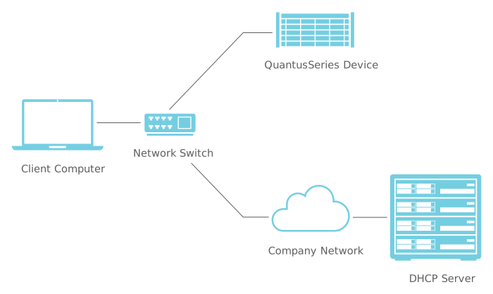
In this configuration, your computer should receive its IP address from the DHCP server. Once the QuantusSeries device is connected to the network, it should also receive an IP address from the DHCP server.
You can now proceed to the next section to Discover your QuantusSeries Device.
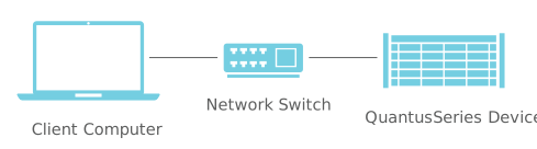
In this configuration, your computer is on an isolated network that does not contain a DHCP server. The device can connect directly with an Ethernet cable or through a network switch.
Here is a diagram of an isolated network through a network switch:
And here is a direct connection: 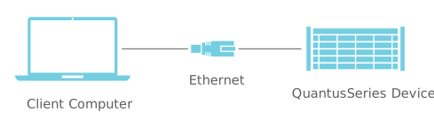
In these configurations, the QuantusSeries device will detect the lack of a DHCP server on the network. It will fall back to the AutoIP protocol and choose a random (free) IP address in the 169.254.xxx.yyy range. If your computer is set up to use DHCP (you are connected to the company network, and you temporarily connect to the device for configuration), then your computer would behave similarly. Your computer should also choose a free IP address in the same range.
If your computer is set up to have a static IP address, you will have to change the address to 169.254.1.1 for the initial configuration.
You can now proceed to the next section to Discover your QuantusSeries Device.
For QuantusSeries devices with optional Wi-Fi, you can have the following network configuration:

The default configuration of the Wi-Fi interface on a QuantusSeries device is Access Point mode with DHCP server enabled. This means that once connected via Wi-Fi, your computer will be given an IP address by the device. Create a wireless connection to the device from the computer by connecting to the SSID Quantus_1234M5678, where the postfix is your device serial number. The security type is “Open”.
You can now proceed to the next section to Discover your QuantusSeries Device.
Before you can communicate with your device, you first have to discover it on your network.
By default, all devices are shipped with the following settings:
Quantus_1234M5678, and the postfix is your device serial number. When connecting to Wi-Fi for the first time, you do not require a password as there is no security selected by default (security type is “Open”). The connecting device will also receive an IP address from the DHCP server running on the Wi-Fi port.Quantus_1234M5678, and the postfix is the device serial number. This name can be changed on the Settings page of the device’s System Settings.All QuantusSeries devices are shipped with mDNS enabled. mDNS is the primary method used to discover devices. There are a couple of options available:
prodIdent field populated with the keyword Quantus. At the moment the only service being advertised is the device’s Systems Settings ("_http._tcp" on port 80), but in the future the list will be more complete.We will use the QDeviceDiscovery tool as an example. The application’s output is a JSON string containing a list of QuantusSeries devices on the network. After turning on your device, open the command line in the QDeviceDiscovery folder located in the QuantusSoftware package. Invoke the application by typing QDeviceDiscovery . The application will discover devices on the network within the next 10 seconds. After that, it will output the list:
> QDeviceDiscovery
{
  "numberOfentries": 1,
  "entries": [
    {
      "deviceName": "Quantus_0718M8880",
      "deviceIp": "10.0.0.202"
    }
  ]
}Once you have discovered the IP address or name of your device, you will be able to access your devices’s System Settings.
QuantusSeries devices have a built-in Web Server which includes System Settings pages. To access the Web Server, open your preferred Web Browser and enter either of the following in the address bar:
http://<SystemIpAddress>, for example, using the device discovered in the previous section http://10.0.0.202http://<Name>.local, for example, using the device discovered in the previous section http://Quantus_0718M8880.localYou will be greeted with the Landing Page. The Landing Page provides basic information about your device and allows you to navigate to your System Settings and/or QAcquire.
The device’s System Settings allows Users to configure the system as a whole:
QAcquire configures, controls and monitors your measurement in a modern and effortless way. It is an alternative method for setting up measurements for clients that do not require OEM Software Packages.
QAcquire is a client-side Web application hosted on the device. You can launch it by opening the Web Browser, navigating to the device’s Landing Page and clicking on the QAcquire link.
With QAcquire the system can be configured online. However, it still requires a streaming client to retrieve the data stream for analysis.
QAcquire can be embedded in your application if your application environment supports embedding a browser. This is done by appending ?embedded to the QAcquire URL. This allows you to embed QAcquire if you want to use it to change all QServer settings without streaming or rendering, in a compact form factor.
QAcquire uses the Fast Fourier Transform (FFT) algorithm to convert time-domain signals into a frequency-domain spectrum.
The process begins by applying a Hanning window to the signal. This windowed signal is then processed by the FFT algorithm, which computes the Discrete Fourier Transform (DFT). After the FFT is applied, the signal’s amplitude is converted to decibels volts (dBV).
The bin width is variable and depends on both the channel sample rate and the frequency range selected by the user. If the entire frequency range is chosen, the FFT size is a minimum of 1024, resulting in 512 frequency bins. However, if the user focuses on a specific frequency range, the FFT size can increase up to a maximum of 8096, resulting in 4048 frequency bins. In the FFT algorithm, the number of frequency bins is halved because the spectrum is symmetrical due to the nature of the Fourier transform for real-valued signals. The bin width is calculated based on the selected frequency range and the current sample rate of the channel.
QDataManager is a Graphical User Interface to Import, Manage, View and Export your Local Storage measurements.
Import measurements from QuantusSeries devices. Using the Import window, you can access all devices on a network, manually or discovered (QDataManager discovers QuantusSeries devices on the network using the QDeviceDiscovery utility). You can view, manage and import Local Storage measurements to a local Depo (a local folder on your computer).
Manage local Depos and measurements. Using the Main window, you can view and manage your measurements and their channels.
Plot your measurement channels. Using the same window, you can view and plot measurement channels. Currently, Analog and Tacho channels are supported. This allows you to quickly see if the recorded measurements are correct.
Export channels to your preferred data format. You can select channels to export into different formats. A CSV exporter is included with a couple of settings. QDataManager supports exporter Plugins, which you can use to format the data in any format needed. You can then use the exported data in other third-party tools for analysing.
The REST API uses HTTP requests for clients to interact with services. This section will show basic interaction with the REST API. A detailed reference can be found in the REST API Reference section.
Note: To demonstrate concepts related to the use of REST APIs we need certain tools. We have opted to use tools that are already installed on new Windows computers. These examples do not reflect how a regular User would use QuantusSoftware, but rather help us present the concepts. We recommend using REST tools and scripting / programming languages that are more suited to this application when doing development.
Since REST APIs use HTTP, the same protocol used by websites on the internet, we can demonstrate some functionality without writing any code.
First, we can check if the system is alive. We can “ping” the REST server using the /info/ping endpoint. Open your internet browser and enter http://SystemIpAddress:8080/info/ping into the URL address bar (replacing the SystemIpAddress with your QuantusSeries device IP Address or the mDNS name). Continuing from the previous section, that would be either of the following:
http://10.0.0.202:8080/info/ping
http://Quantus_0718M8880.local:8080/info/ping
The system should respond with the following JSON string:
{
    "Code": 0,
    "Message":  "System is operational"
}
Another useful endpoint is the /endpoints endpoint which will return a list of endpoints supported by QuantusSoftware. Here is a snippet of the response for this endpoint:
[
    {
        "Action":   "GET",
        "Path": "system/settings/",
        "QueryString":  "",
        "Info": "Returns the cached system settings",
        "Example URL":  "http://<SystemIpAddress>:8080/systemSettings/"
    },
    {
        "Action":   "PUT",
        "Path": "system/settings/apply/",
        "QueryString":  "",
        "Info": "Applies the system settings that was set using PUT /itemSettings"
    },
    {
        "Action":   "GET",
        "Path": "item/operationMode/",
        "QueryString":  "?itemId=X",
        "Info": "Returns the cached operation mode of the item specified by the itemId query string",
        "Example URL":  "http://<SystemIpAddress>:8080/operationMode/?itemId=X"
    },
  ...
],
Writing back to the server is a bit more involved. We will have to use a scripting language for the example. Generally any language would work, but the only one that does not require installing anything on Windows is Powershell.
Open the command line and enter the following (replace the IP with your system IP or name):
powershell Invoke-WebRequest "http://10.0.0.202:8080/item/settings/?itemId=1" -OutFile "itemSettings.json"This will read system settings into the itemSettings.json file. You can open this file in your favourite text editor. You will be presented with a tree structure of the system configuration. Each node in the tree has a similar structure, which is a list of Settings, SupportedValues for the setting and the current Value of the setting (which is the Id in the SupportedValues list). Below is an example of what the output would be:
{
  "System": {
    "DeviceId": 1,
    "DeviceName": "PQ30G2",
    "DeviceType": "Controller",
    "Info": [],
    "Settings": [
      {
        "Name": "Master Sampling Rate",
        "Type": "Enumeration",
        "SupportedValues": [
          {
            "Id": 0,
            "Description": "131072 Hz"
          },
          {
            "Id": 1,
            "Description": "160000 Hz"
          },
          {
            "Id": 2,
            "Description": "163840 Hz"
          },
          {
            "Id": 3,
            "Description": "176400 Hz"
          },
          {
            "Id": 4,
            "Description": "192000 Hz"
          },
          {
            "Id": 5,
            "Description": "200000 Hz"
          },
          {
            "Id": 6,
            "Description": "204800 Hz"
          }
        ],
        "Value": 0
      }
    ],
...
This system is currently running at a Master Sample Rate of 131072 Hz. Let’s modify the Sample Rate to 204800 by changing the Value field to 6. Save the file and run the following in the command-line:
powershell Invoke-WebRequest "http://10.0.0.202:8080/item/settings/?itemId=1" -Method Put -infile "itemSettings.json"The settings are now cached on the system, but need to be applied for the change to happen:
powershell Invoke-WebRequest "http://10.0.0.202:8080/system/settings/apply" -Method PutThe system should now be running at a Master Sample Rate of 204800.
For performance reasons, the data stream cannot be REST. The data stream format is a proprietary binary format. See Data Streaming Reference for in-depth information regarding how to read the data stream.
This section will explain the purpose and usage of the tools contained in the QuantusSoftware package.
The QDeviceDiscovery application discovers QuantusSeries devices on the network using mDNS. It searches for devices for a specific time. This time is an input parameter on the application with a default of 5 seconds. The output is a list of devices in JSON format.
QDeviceDiscovery [OPTIONS]

Options
--help          Help Screen
--timeout Timeout in seconds to wait for devices to be detected on the network. The default is 5s.Basic usage and output:
QDeviceDiscovery.exe
{
        "numberOfentries":      1,
        "entries":      [
            {
                        "deviceName":   "Quantus_0718M8880",
                        "deviceIp":     "10.0.0.202"
            }
        ]
}There are a couple of ways to upgrade the software of a QuantusSeries device. The first is by using the device’s System Settings (from the Landing Page, navigate to System Settings).
The second is the QSoftwareUpgrade utility. It is a simple command-line utility that will upgrade the given device. It can easily be incorporated into the software package being used with the QuantusSeries device.
A software upgrade can take several minutes to complete. At the moment the software does not provide any feedback on the progress of the upgrade.
QSoftwareUpgrade.exe [options] DeviceIpOrName
Ip address or device name is required.
Parameter Options:
  --help                Help Screen
  --filename arg        QSoftware package file name (can include a path), leave
                        blank to use the default
  --upgradePassword arg Password to upgrade the software, leave blank to use
                        the default password
  --progress            Display the progress of the Upgrade process
  --pretty              Display output text in pretty human readable text
instead of JSON formatThe application can return one of the following values:
UpgradeSuccessful = 0,
GeneralFailure = -1,
InvalidDeviceIpAddress = -2,
FailedToLoginToDevice = -3,
InvalidUpgradePassword = -4,
InvalidFirmwareFile = -5,
IncompatibleFirmwareFile = -6,
InvalidCommandLineArguments = -8,
FailedToOpenFile = -9
It can also return a JSON object with the code and a description:
{
        "Result":       -3,
        "Description":  "Software upgraded failed, unable to open the specified software package file"
}Minimum parameters specified:
QSoftwareUpgrade.exe 192.168.5.151Specifying upgrade file and password:
QSoftwareUpgrade.exe --upgradePassword MySecretPassword --filename C:\Users\MyName\Quantus\MyCustomQSoftwarePackageName.cmp 192.168.5.151Progress of the upgrade can be obtained using the --progress parameter. The progress is given in JSON format for applications that want to parse the output:
QSoftwareUpgrade.exe --progress 192.168.5.151 Each progress update will have a JSON object followed by a new line. The JSON object has the following format:
{
    "UpgradeStage":         4,
    "StageDescription":     "Software Upgrade Complete",
    "UpgradeStageProgress": 0,
    "Result":               0,
    "Description":          "Software already up to date"
}
QSoftwareUpgrade can also display the progress in the terminal/command-line by adding the --pretty parameter:
QSoftwareUpgrade.exe --progress --pretty 192.168.5.151 Any QuantusSeries device can be reset back to its default settings. This is useful if the device has irreversible invalid settings.
To reset a MICROQ to default settings, keep the Power On/ Off button pressed down for about 3 seconds. Wait for the PoE and Battery LEDs to turn solid orange, then release the power button. Repeat this action three times within 15 seconds. If successful, the LEDs will slowly flash orange after the third sequence. The reset settings will be available once the MICROQ has been initialized.
The DECAQ reset procedure differs from that of the MICROQ. Using the Power On / Off button, scroll through the options until the device display shows DFLT. Press the OK button on the device and when prompted by SURE on the display, press the OK button again.
Default settings for a QuantusSeries device are as follows:
Ethernet port: The IP Address is obtained using DHCP. If no DHCP server is available, the device will fall back to AutoIP. It will automatically assign a free IP in the 169.254.xxx.yyy range.
Wi-Fi port: By default, the Wi-Fi is set up in Access Point mode. The Wi-Fi SSID is Quantus_1234M5678 and the postfix is your device serial number. When connecting to Wi-Fi for the first time, no password is required. The default security is set to type “Open”. The connecting device will also receive an IP address from the DHCP server running on the Wi-Fi port.
Name: Your device name will be in the format Quantus_1234M5678. The postfix is the device serial number. This name can be changed on the Settings page of your device’s System Settings.
QServer: The default settings for each node will be set, as specified in the REST API Reference
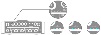
These three blue LEDs indicate the progress of system initialization (1 - 3). Each LED will blink and then turn solid blue until all three LEDs are on, indicating that initialization is complete.
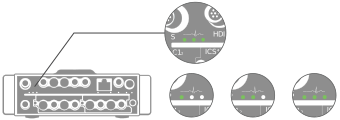
Once the system has finished the boot process the LED sequence will typically take place in the following order:
The LEDs will indicate some error information should something go wrong.
| First | Second | Third | Error description |
|---|---|---|---|
| Solid green | Solid red | No color | Apply settings have failed |
| Solid green | Solid green | Solid red | Buffer overflow, data streaming has been disabled |
Various messages will be displayed on the User Interface display to indicate the progress of system initialization. The message Idle indicates that initialization is complete.
Once the system has finished the boot process the QServer will display the following messages:
The REST API uses HTTP requests for clients to interact with services.
The REST API has resources with which Users can interact. Each resource can be accessed through a request via its endpoint. In essence, an endpoint is the URI that links to a given resource. HTTP request methods dictate how a User wants to interact with the resource:
This section will provide information about all endpoints / resources available on the QuantusSoftware REST API. It will also specify which methods are supported (GET, POST, etc.).
The REST API follows HTTP status code convention.
The following error codes can be expected:
Additionally, if an error occurs or the endpoint has a response the User should take note of, a JSON status message with the following format will be returned:
{
    "TypeCode" : 2,
    "StatusCode" : 5,
    "Message" : "Invalid item id, refer to the systemSettings/itemList for an overview"
}| Field | Description | Options |
|---|---|---|
| TypeCode | The type of message | 0 - Status 1 - Information 2 - Error |
| StatusCode | Enumeration that corresponds to the message | |
| Message | User-friendly string that can be displayed to the User to inform them about the error / info |
| Status code | Http code | Message |
|---|---|---|
| 0 | 400 | General Failure |
| 1 | 200 | Success |
| 2 | 400 | Settings was not updated, due to an invalid configuration, possible enumeration out of range |
| 3 | 200 | Settings was updated successfully |
| 4 | 200 | Settings are valid, but applying them will restart the measurement |
| 5 | 400 | Invalid item id, refer to the systemSettings/itemList for an overview |
| 6 | 400 | API major version incompatibility |
| 7 | 404 | Action was not found |
| 8 | 400 | The requested action is only allowed for channels |
| 9 | 400 | The requested action is only allowed for analog output channels |
| 10 | 400 | The requested action is only allowed for data channels |
| 11 | 400 | The requested action cannot be completed as the channel is disabled |
| 12 | 400 | This channel does not support test signals |
| 13 | 400 | This channel does not support TEDS |
| 14 | 200 | Applying these settings will affect other items/modules/channels |
| 15 | 400 | This item does not support auto zero |
| 16 | 500 | Failed to auto zero channel/system |
| 17 | 500 | Failed to read the module status register |
| 18 | 400 | This item does not support the reading of status registers |
| 19 | 400 | The requested action is only allowed for CAN FD channels |
| 20 | 400 | The requested action is only allowed when the CAN FD channel is in PARTICIPATE mode |
| 21 | 400 | The requested action is only allowed for WSB channels |
| 22 | 400 | The requested action is only allowed for GPS channels |
| 23 | 400 | Invalid settings, this string will contain a message with details about the invalid settings |
| 24 | 400 | Error, this string will contain a message with details about the error |
| Endpoint | Method | Parameters | Body | Description |
|---|---|---|---|---|
| /version | GET | Returns the current version of QuantusSoftware running on the system | ||
| /info/ping | GET | Returns a status message of “System is Operational” once the QuantusSoftware is fully initialized and ready for use | ||
| /endpoints | GET | Returns the list of supported endpoints |
| Endpoint | Method | Parameters | Body | Port | Description |
|---|---|---|---|---|---|
| /system/settings/resetToDefaults | GET | 8080 | Resets all the nodes to their default settings as described in REST API Reference | ||
| /system/time | GET | Current system time | 8080 | Returns the system time as year, month, day, hour, minutes and seconds | |
| /system/time | PUT | New system time | 8080 | Sets the system time to the year, month, day, hour, minutes and seconds specified in the body. | |
| /system/upTime | GET | Current system up-time | 8080 | Returns the system up-time in seconds | |
| /system/shutdown | POST | 80 | Shuts down the system | ||
| /system/restart | POST | 80 | Restarts the system | ||
| /system/fanSpeed | POST | “fanSpeed”: x where x can be 0 : Off 1 : Low 2 : Medium 3 : High 4 : Maximum 5 : Automatic - Low noise 6 : Automatic - Low temperature |
80 | Set the fan speed | |
| /system/calibrate | PUT | 8080 | Calibrates the system at the current conditions |
| Endpoint | Method | Port | Description |
|---|---|---|---|
| /SystemStatus | GET | 80 | Accessible on port 80 while QuantusSoftware is initialising and calibrating. Returns the boot percentage, system state and application state. |
| /Version | GET | 80 | Returns the current version of QuantusSoftware running on the system. |
| /SystemTemperature | GET | 80 | Returns the current temperature of the system in degrees Celsius. |
| /SystemSynchronisation | GET | 80 | Returns the synchronisation status of the system. |
| Endpoint | Method | Parameters | Body | Description |
|---|---|---|---|---|
| /dataStream/setup | GET | Returns the data streaming setup containing the IP addresses and port numbers used by the streaming engine. Note: Please use the “IPAddresses”, “TCPPort” and “WebSocketPort” fields since “TCP” and “Websocket” will be deprecated in future releases. | ||
| /dataStream/suspend | PUT | Suspends the data stream, discarding all data until /dataStream/resume is called | ||
| /dataStream/resume | PUT | Resumes the data stream |
| Endpoint | Method | Parameters | Body | Description |
|---|---|---|---|---|
| /item/list | GET | Returns a list of all items in the system, each with item name, id and type | ||
| /item/operationMode | GET | /?itemId=x | Returns the operation mode for a specified item | |
| /item/operationMode | PUT | /?itemId=x | New operation mode for item | Updates the specified item with a given operation mode |
| /item/settings | GET | /?itemId=x | Returns item settings for a specified item | |
| /item/settings | PUT | /?itemId=x | New settings for item | Updates specified item with provided settings |
| /system/settings | GET | Returns settings for all devices | ||
| /system/settings/apply | PUT | Applies and reconfigures the system with new settings | ||
| /tedsInfo | GET | /?itemId=x | Returns TEDS info for a specified item. TEDS info is a raw byte array as stored on the sensor connected to the item. | |
| /autoZero/settings | GET | /?itemId=x | Returns Auto-Zero settings of a specified item | |
| /autoZero/settings | PUT | /?itemId=x | New Auto-Zero settings | Updates Auto-Zero settings of a specified item |
| /autoZero/settings/apply | PUT | Empty or /?itemId=x |
Applies Auto-Zero settings either system-wide if no query string was provided or to the item specified by the query string |
When looking at measurement endpoints from the previous section, it should be noted that there are endpoints that contain the word “item”. Due to the modular nature of QuantusSeries systems, it is best to visualise each system and its components as a parent / children (hierarchical) structure. Each of the components are named “items” in the REST API.
A simple system would have the following structure:

In this system, the Controller, Signal Conditioners, Modules and channels are all items. They are all accessible resources in the REST API. Most items will have settings that can be modified, some might not have any. Settings on the Parent item might have an impact on the performance or configuration of the Children.
The /system/settings endpoint will present all the items in a tree data structure. The /item/list will present all items in the system (without their settings) in a linear list.
It is recommended that Users begin by configuring measurements at the root node and working their way down the tree.
| Type | Identifier |
|---|---|
| Controller | 0 |
| Signal Conditioner | 1 |
| Module | 2 |
| Channel | 4 |
| Type | Identifier |
|---|---|
| MicroQ | 30100 |
| PQ45 | 30110 |
| Type | Identifier |
|---|---|
| SC42 G2 | 10070 |
| SC42S G2 | 10080 |
| SC42S G2 | 10086 |
| SC104 | 10101 |
| SC45 | 10087 |
| Type | Identifier |
|---|---|
| CHG42S9 | 146 |
| DCH42S2 | 149 |
| ALO42S4 | 151 |
| FLX422 | 155 |
| CAN42S2 | 157 |
| GPS42S6 | 163 |
| GPS450 | 164 |
| FLX450 | 166 |
| CAN450 | 167 |
| THM427 | 170 |
| THM450 | 171 |
| MIC42X7 | 180 |
| ICS42L5 | 182 |
| CHS42X4 | 184 |
| ICP450 | 188 |
| ICT454 | 189 |
| ALO450 | 196 |
| ICP4211 | 211 |
| ICS421 | 213 |
| ICS425 | 217 |
| ICT426 | 218 |
| TAC221 | 222 |
| WSB42X2 | 227 |
| WSB42X5 | 229 |
| WSB42X6 | 230 |
| ICS450 | 232 |
| ICM450 | 233 |
| VIM450 | 235 |
| Empty | 240 |
| Unsupported | 253 |
| XMC237 | 20005 |
| ICP42S11 | 65747 |
| ICT42S6 | 65754 |
| Type | Identifier |
|---|---|
| CAN42S2 | 0 |
| XMC237 ICP | 7 |
| ICP4211 | 11 |
| ICP42S11 | 12 |
| ICS421 | 13 |
| ICS425 | 15 |
| ICT42S6 Tacho | 16 |
| ICT426 Tacho | 17 |
| ICT42S6 Scope | 18 |
| ICT426 Scope | 19 |
| ICT42S6 ICP | 20 |
| ICT426 ICP | 21 |
| TAC221 Tacho | 23 |
| ALO42S4 | 24 |
| WSB42X2 | 30 |
| TAC221 Scope | 33 |
| XMC237 CAN FD | 34 |
| XMC237 GPS | 36 |
| CHS42X4 | 40 |
| DCH42S2 | 41 |
| THM427 | 45 |
| ICS42L5 | 46 |
| MIC42X7 | 47 |
| WSB42X5 | 51 |
| WSB42X6 | 52 |
| GPS42S6 | 53 |
| CHG42S9 | 54 |
| ALO450 | 55 |
| DCH450 | 56 |
| ICS450 | 57 |
| ICM450 | 58 |
| THM450 | 61 |
| GPS450 | 62 |
| CAN450 | 63 |
| FLX450 | 64 |
| FLX422 | 75 |
| ICP450 | 76 |
| VIM450 | 77 |
| ICT454 ICP | 78 |
| ICT454 SCOPE | 79 |
| ICT454 TACHO | 80 |
| Unsupported | 253 |
QuantusSeries devices are feature-rich and thus have a lot of settings. To ease configuration, settings are grouped into “operation modes”. These modes will change the mode of operation of an item (Module or channel) and allow Users to change a subset of settings relevant to that mode.
Here is a sequence diagram of a typical setup using operation modes:

QuantusSoftware can query the Dallas/Maxim memory chips included in sensors compliant with the IEEE 1451.4 TEDS standard. The information returned by QuantusSoftware is a byte array containing the contents of the memory chip.
TEDS data is very compact and not byte aligned. Each field has a specific bit length and decoding method as described in the standard. QuantusSoftware does not interpret the information in the byte array. This must be done by the software receiving the QuantusSoftware TEDS response.
A channel’s TEDS data can be obtained by calling the GET /tedsInfo endpoint. The endpoint will return the TEDS data in a JSON byte array:
{
    "Name": "TEDS",
    "Value":    [40, 129, 35, 200, 0, 0, 0, 80, 0, 255, ... , 255]
}The channel Auto-Zero can be used to clear and zero any offsets present within the channel hardware only (system) or the entire signal channel (system and sensor).
After a channel Auto-Zero, each channel will be restored to pre-Auto-Zero channel settings.
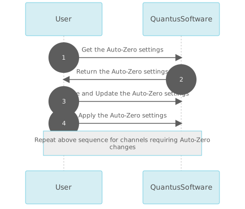
Channel Auto-Zero settings can be obtained by reading from the /autoZero/settings endpoint. The settings can be applied by updating the setting with the /autoZero/settings endpoint and calling /autoZero/settings/apply. Auto-Zero settings can be seen as an action that can be applied if there is a perceived offset in the data:
| Setting | Description | Options | Default |
|---|---|---|---|
| Auto-Zero Level | Set the Auto-Zero level to be applied on the channel | Disabled System and Sensor System Only |
Disabled |
| Auto-Zero Average Time | Set the length of data averaging time to determine the data offset | Quick 1 second average 2 second average 5 second average |
Quick |
Here is a sequence diagram of a typical Auto-Zero action:
The Controller Item is the main entry point for the settings structure and is responsible for hosting the Signal Conditioning boards, Modules and Channels.
Depending on the configuration, the Controller board might have additional features:
* WiFi for remote access
* SSD for local storage
* Battery for an uninterrupted power supply
Gets or sets the Controller operation mode. The active Module operation mode can be retrieved by reading from the /operationMode/ and modified by writing to the /operationMode/ endpoint. See the tables below for all supported mode options and mode settings.
| Settings | Options | Default |
|---|---|---|
| Operation Mode | Disabled Enabled |
Enabled |
This operation mode will set the Controller in a “powered on” state. The settings below can be retrieved by reading from the /itemSettings/ and modified by writing to the /itemSettings/ endpoint.
| Settings | Description | Options | Default |
|---|---|---|---|
| Master Sampling Rate | Gets or sets the system master (base) sample rate in Hz. | 131072 Hz 160000 Hz 163840 Hz 176400 Hz 192000 Hz 200000 Hz 204800 Hz |
204800 Hz |
| Analog Data Streaming Format | Gets or sets the system streaming mode for analog channels. | Processed Raw |
Processed |
The ALO42S4 Module provides four independent output channels for the generation of analog signals. Each channel also incorporates Status Input and Output signals, enabling further communication with external equipment for applications such as test supervision or workflow control.
The Module can be used for applications such as:
Gets or sets the Module operation mode. The active Module operation mode can be retrieved by reading from the /operationMode/ and modified by writing to the /operationMode/ endpoint. See the tables below for all supported mode options and mode settings.
| Settings | Options | Default |
|---|---|---|
| Operation Mode | Enabled Disabled Mirror Left Module Arbitrary Waveform |
Enabled |
This operation mode will set the Module in a “powered on” state and allow use of the built-in function generator.
The settings below can be retrieved by reading from the /itemSettings/ and modified by writing to the /itemSettings/ endpoint.
| Settings | Description | Options | Default |
|---|---|---|---|
| Grounding | Gets or sets the grounding isolation switch on the Module. | Floating Grounded |
Floating |
This operation mode will set the Module in a “powered on” state and stream the sampled data of the Module to the left. Some restrictions do apply:
The channel mapping will recursively assign the data stream from first Enabled channel of the Module to the left, to the first available channel on the ALO42S4. Disabled channels are not assigned and skipped over.
The settings below can be retrieved by reading from the /itemSettings/ and modified by writing to the /itemSettings/ endpoint.
| Settings | Description | Options | Default |
|---|---|---|---|
| Grounding | Gets or sets the grounding isolation switch on the Module. | Floating Grounded |
Floating |
This operation mode will set the Module in a “powered on” state and allow streaming of user provided data.
The settings below can be retrieved by reading from the /itemSettings/ and modified by writing to the /itemSettings/ endpoint.
| Settings | Description | Options | Default |
|---|---|---|---|
| Sample Rate | Gets or sets this Module’s channels’ effective sample rate as a division of master sample rate. | MSR Divide by 64 MSR Divide by 1 MSR Divide by 2 MSR Divide by 4 MSR Divide by 8 MSR Divide by 16 MSR Divide by 32 |
MSR Divide by 64 |
| Grounding | Gets or sets the grounding isolation switch on the Module. | Floating Grounded |
Floating |
Some additional endpoints are available for this Item node.
This endpoint returns block size required by the module. When streaming data the user will be required
send at least the block size number of bytes.
| Endpoint | Method | Parameters | Body | Description |
|---|---|---|---|---|
| /alo/blockSize/ | GET | /?itemId=X | BlockSize | The block size to be used when streaming |
Each channel operates independently from one another. Some restrictions do apply:
Gets or sets the channel operation mode. The active channel operation mode can be retrieved by reading from the /operationMode/ and modified by writing to the /operationMode/ endpoint. See the tables below for all supported mode options and mode settings.
| Settings | Options | Default |
|---|---|---|
| Operation Mode | DC Generator Disabled Sine Wave Generator Square Wave Generator Triangular Wave Generator White Noise Generator Mirror Left Module Streaming Buffered |
DC Generator |
This operation mode will configure the signal generator for a DC waveform. The settings below can be retrieved by reading from the /itemSettings/ and modified by writing to the /itemSettings/ endpoint.
| Settings | Description | Options | Default |
|---|---|---|---|
| Signal Connection | Gets or sets the signal connection state of the signal line on this channel. | Connected Grounded |
Connected |
| Signal Amplitude | Gets or sets the signal amplitude in Volts. | -9.999 < value < 10 | 0 |
| Signal Amplitude Change Time | Gets or sets the signal amplitude change time in seconds. | 0 < value < 3600 | 0 |
| Output Voltage Level | Gets or sets the output voltage level of the fixed DC voltage output line. | 5 V Out 12 V Out |
5 V Out |
| Module Status Output | Gets or sets the module status output. | Open circuit Short circuit Output Voltage |
Open circuit |
This operation mode will configure the signal generator for an AC waveform. The settings below can be retrieved by reading from the /itemSettings/ and modified by writing to the /itemSettings/ endpoint.
| Settings | Description | Options | Default |
|---|---|---|---|
| Signal Connection | Gets or sets the signal connection state of the signal line on this channel. | Connected Grounded |
Connected |
| Signal Amplitude | Gets or sets the signal amplitude in Volts. | -9.999 < value < 10 | 0 |
| Signal Amplitude Change Time | Gets or sets the signal amplitude change time in seconds. | 0 < value < 3600 | 0 |
| Signal Frequency | Gets or sets the signal frequency in Hertz. | 0 < value < 10000 | 0 |
| Signal Frequency Change Time | Gets or sets the signal frequency transition duration in seconds. When a signal offset is specified, this time period controls the offset transition duration as well. | 0 < value < 3600 | 0 |
| Signal Offset | Gets or sets an offset to the signal in Volts. | -9.999 < value < 10 | 0 |
| Signal Phase | Gets or sets the starting phase of the generated signal in relation to the other channels. | -360 < value < 360 | 0 |
| Output Voltage Level | Gets or sets the output voltage level of the fixed DC voltage output line. | 5 V Out 12 V Out |
5 V Out |
| Extended Frame | Gets or sets the module status output. | Open circuit Short circuit Output Voltage |
Open circuit |
This operation mode will configure the signal generator for a square waveform. The settings below can be retrieved by reading from the /itemSettings/ and modified by writing to the /itemSettings/ endpoint.
| Settings | Description | Options | Default |
|---|---|---|---|
| Signal Connection | Gets or sets the signal connection state of the signal line on this channel. | Connected Grounded |
Connected |
| Signal Amplitude | Gets or sets the signal amplitude in Volts. | -9.999 < value < 10 | 0 |
| Signal Amplitude Change Time | Gets or sets the signal amplitude change time in seconds. | 0 < value < 3600 | 0 |
| Signal Frequency | Gets or sets the signal frequency in Hertz. | 0 < value < 10000 | 0 |
| Signal Frequency Change Time | Gets or sets the signal frequency transition duration in seconds. When a signal offset is specified, this time period controls the offset transition duration as well. | 0 < value < 3600 | 0 |
| Signal Offset | Gets or sets an offset to the signal in Volts. | -9.999 < value < 10 | 0 |
| Signal Phase | Gets or sets the starting phase of the generated signal in relation to other channels. | -360 < value < 360 | 0 |
| Output Voltage Level | Gets or sets the output voltage level of the fixed DC voltage output line. | 5 V Out 12 V Out |
5 V Out |
| Extended Frame | Gets or sets the module status output. | Open circuit Short circuit Output Voltage |
Open circuit |
This operation mode will configure the signal generator for a triangular waveform. The settings below can be retrieved by reading from the /itemSettings/ and modified by writing to the /itemSettings/ endpoint.
| Settings | Description | Options | Default |
|---|---|---|---|
| Signal Connection | Gets or sets the signal connection state of the signal line on this channel. | Connected Grounded |
Connected |
| Signal Amplitude | Gets or sets the signal amplitude in Volts. | -9.999 < value < 10 | 0 |
| Signal Amplitude Change Time | Gets or sets the signal amplitude change time in seconds. | 0 < value < 3600 | 0 |
| Signal Frequency | Gets or sets the signal frequency in Hertz. | 0 < value < 10000 | 0 |
| Signal Frequency Change Time | Gets or sets the signal frequency transition duration in seconds. When a signal offset is specified, this time period controls the offset transition duration as well. | 0 < value < 3600 | 0 |
| Signal Offset | Gets or sets an offset to the signal in Volts. | -9.999 < value < 10 | 0 |
| Signal Phase | Gets or sets the starting phase of the generated signal in relation to other channels. | -360 < value < 360 | 0 |
| Output Voltage Level | Gets or sets the output voltage level of the fixed DC voltage output line. | 5 V Out 12 V Out |
5 V Out |
| Extended Frame | Gets or sets the module status output. | Open circuit Short circuit Output Voltage |
Open circuit |
This operation mode will configure the signal generator for a white noise waveform. The settings below can be retrieved by reading from the /itemSettings/ and modified by writing to the /itemSettings/ endpoint.
| Settings | Description | Options | Default |
|---|---|---|---|
| Signal Connection | Gets or sets the signal connection state of the signal line on this channel. | Connected Grounded |
Connected |
| Signal Amplitude | Gets or sets the signal amplitude in Volts. | -9.999 < value < 10 | 0 |
| Signal Amplitude Change Time | Gets or sets the signal amplitude change time in seconds. | 0 < value < 3600 | 0 |
| Signal Offset | Gets or sets an offset to the signal in Volts. | -9.999 < value < 10 | 0 |
| Signal Phase | Gets or sets the starting phase of the generated signal in relation to other channels. | -360 < value < 360 | 0 |
| Output Voltage Level | Gets or sets the output voltage level of the fixed DC voltage output line. | 5 V Out 12 V Out |
5 V Out |
| Extended Frame | Gets or sets the module status output. | Open circuit Short circuit Output Voltage |
Open circuit |
This operation mode will configure the signal generator to stream the sampled data from the Module to the left. The data samples are scaled to half of the 10 Vpp full scale output. As an example: for a 10 V input range the mirrored signal will be scaled to 5 V on the ALO42S4 channel, 100 mV input range will also be scaled to 5 V. This allows the ALO42S4 to generate signal which matches the full dynamic range of the sampling channel.
There are no settings available.
This operation mode allows the user to continuously stream data samples.
| Settings | Description | Options | Default |
|---|---|---|---|
| Fallback Mode | Gets or sets the output fallback mode when no data is available to stream | Fade to zero Zero |
Fade to zero |
| Output Voltage Level | Gets or sets the output voltage level of the fixed DC voltage output line. | 5 V Out 12 V Out |
5 V Out |
| Extended Frame | Gets or sets the module status output. | Open circuit Short circuit Output Voltage |
Open circuit |
This operation mode allows the user to preload data samples.
| Settings | Description | Options | Default |
|---|---|---|---|
| Sample Count | The total number of samples in the buffered signal. | 1 < value < 6144000 | 1024 |
| Output Voltage Level | Gets or sets the output voltage level of the fixed DC voltage output line. | 5 V Out 12 V Out |
5 V Out |
| Extended Frame | Gets or sets the module status output. | Open circuit Short circuit Output Voltage |
Open circuit |
Some additional endpoints are available for this Item node.
This endpoint returns the port number to which a client needs to connect in order to stream data to
the ALO42S4 channel. Note the port number is dynamic, so always query it before connecting.
| Endpoint | Method | Parameters | Body | Description |
|---|---|---|---|---|
| /alo/port/ | GET | /?itemId=X | Port | The port number to be used when streaming |
This endpoint clears the data in the streaming buffer, effectively returning the data stream to the
chosen fallback mechanism.
| Endpoint | Method | Parameters | Body | Description |
|---|---|---|---|---|
| /alo/clearData/ | PUT | /?itemId=X | Clears the data streaming buffer |
The ALO450 Module provides four independent output channels for the generation of analog signals. Each channel also incorporates Status Input and Output signals, enabling further communication with external equipment for applications such as test supervision or workflow control.
The Module can be used for applications such as:
Gets or sets the Module operation mode. The active Module operation mode can be retrieved by reading from the /operationMode/ and modified by writing to the /operationMode/ endpoint. See the tables below for all supported mode options and mode settings.
| Settings | Options | Default |
|---|---|---|
| Operation Mode | Enabled Disabled Mirror Left Module Arbitrary Waveform |
Enabled |
This operation mode will set the Module in a “powered on” state. The settings below can be retrieved by reading from the /itemSettings/ and modified by writing to the /itemSettings/ endpoint.
| Settings | Description | Options | Default |
|---|---|---|---|
| Grounding | Gets or sets the grounding isolation switch on the Module. | Floating Grounded |
Floating |
This operation mode will set the Module in a “powered on” state and stream the sampled data of the Module to the left. Some restrictions do apply:
The channel mapping will recursively assign the data stream from first Enabled channel of the Module to the left, to the first available channel on the ALO450. Disabled channels are not assigned and skipped over.
The settings below can be retrieved by reading from the /itemSettings/ and modified by writing to the /itemSettings/ endpoint.
| Settings | Description | Options | Default |
|---|---|---|---|
| Grounding | Gets or sets the grounding isolation switch on the Module. | Floating Grounded |
Floating |
This operation mode will set the Module in a “powered on” state and allow streaming of user provided data.
The settings below can be retrieved by reading from the /itemSettings/ and modified by writing to the /itemSettings/ endpoint.
| Settings | Description | Options | Default |
|---|---|---|---|
| Sample Rate | Gets or sets this Module’s channels’ effective sample rate as a division of master sample rate. | MSR Divide by 64 MSR Divide by 1 MSR Divide by 2 MSR Divide by 4 MSR Divide by 8 MSR Divide by 16 MSR Divide by 32 |
MSR Divide by 64 |
| Grounding | Gets or sets the grounding isolation switch on the Module. | Floating Grounded |
Floating |
Some additional endpoints are available for this Item node.
This endpoint returns block size required by the module. When streaming data the user will be required
send at least the block size number of bytes.
| Endpoint | Method | Parameters | Body | Description |
|---|---|---|---|---|
| /alo/blockSize/ | GET | /?itemId=X | BlockSize | The block size to be used when streaming |
Each channel operates independently from one another. Some restrictions do apply:
Gets or sets the channel operation mode. The active channel operation mode can be retrieved by reading from the /operationMode/ and modified by writing to the /operationMode/ endpoint. See the tables below for all supported mode options and mode settings.
| Settings | Options | Default |
|---|---|---|
| Operation Mode | DC Generator Disabled Sine Wave Generator Square Wave Generator Triangular Wave Generator White Noise Generator Mirror Left Module Streaming Buffered |
DC Generator |
This operation mode will configure the signal generator for a DC waveform. The settings below can be retrieved by reading from the /itemSettings/ and modified by writing to the /itemSettings/ endpoint.
| Settings | Description | Options | Default |
|---|---|---|---|
| Signal Connection | Gets or sets the signal connection state of the signal line on this channel. | Connected Grounded |
Connected |
| Signal Amplitude | Gets or sets the signal amplitude in Volts. | -9.999 < value < 10 | 0 |
| Signal Amplitude Change Time | Gets or sets the signal amplitude change time in seconds. | 0 < value < 3600 | 0 |
| Output Voltage Level | Gets or sets the output voltage level of the fixed DC voltage output line. | 5 V Out 12 V Out |
5 V Out |
| Module Status Output | Gets or sets the module status output. | Open circuit Short circuit Output Voltage |
Open circuit |
This operation mode will configure the signal generator for an AC waveform. The settings below can be retrieved by reading from the /itemSettings/ and modified by writing to the /itemSettings/ endpoint.
| Settings | Description | Options | Default |
|---|---|---|---|
| Signal Connection | Gets or sets the signal connection state of the signal line on this channel. | Connected Grounded |
Connected |
| Signal Amplitude | Gets or sets the signal amplitude in Volts. | -9.999 < value < 10 | 0 |
| Signal Amplitude Change Time | Gets or sets the signal amplitude change time in seconds. | 0 < value < 3600 | 0 |
| Signal Frequency | Gets or sets the signal frequency in Hertz. | 0 < value < 10000 | 0 |
| Signal Frequency Change Time | Gets or sets the signal frequency change time in seconds. | 0 < value < 3600 | 0 |
| Signal Offset | Gets or sets an offset to the signal in Volts. | -9.999 < value < 10 | 0 |
| Signal Phase | Gets or sets the starting phase of the generated signal in relation to the other channels. | -360 < value < 360 | 0 |
| Output Voltage Level | Gets or sets the output voltage level of the fixed DC voltage output line. | 5 V Out 12 V Out |
5 V Out |
| Module Status Output | Gets or sets the module status output. | Open circuit Short circuit Output Voltage |
Open circuit |
This operation mode will configure the signal generator for a square waveform. The settings below can be retrieved by reading from the /itemSettings/ and modified by writing to the /itemSettings/ endpoint.
| Settings | Description | Options | Default |
|---|---|---|---|
| Signal Connection | Gets or sets the signal connection state of the signal line on this channel. | Connected Grounded |
Connected |
| Signal Amplitude | Gets or sets the signal amplitude in Volts. | -9.999 < value < 10 | 0 |
| Signal Amplitude Change Time | Gets or sets the signal amplitude change time in seconds. | 0 < value < 3600 | 0 |
| Signal Frequency | Gets or sets the signal frequency in Hertz. | 0 < value < 10000 | 0 |
| Signal Frequency Change Time | Gets or sets the signal frequency change time in seconds. | 0 < value < 3600 | 0 |
| Signal Offset | Gets or sets an offset to the signal in Volts. | -9.999 < value < 10 | 0 |
| Signal Phase | Gets or sets the starting phase of the generated signal in relation to other channels. | -360 < value < 360 | 0 |
| Output Voltage Level | Gets or sets the output voltage level of the fixed DC voltage output line. | 5 V Out 12 V Out |
5 V Out |
| Module Status Output | Gets or sets the module status output. | Open circuit Short circuit Output Voltage |
Open circuit |
This operation mode will configure the signal generator for a triangular waveform. The settings below can be retrieved by reading from the /itemSettings/ and modified by writing to the /itemSettings/ endpoint.
| Settings | Description | Options | Default |
|---|---|---|---|
| Signal Connection | Gets or sets the signal connection state of the signal line on this channel. | Connected Grounded |
Connected |
| Signal Amplitude | Gets or sets the signal amplitude in Volts. | -9.999 < value < 10 | 0 |
| Signal Amplitude Change Time | Gets or sets the signal amplitude change time in seconds. | 0 < value < 3600 | 0 |
| Signal Frequency | Gets or sets the signal frequency in Hertz. | 0 < value < 10000 | 0 |
| Signal Frequency Change Time | Gets or sets the signal frequency change time in seconds. | 0 < value < 3600 | 0 |
| Signal Offset | Gets or sets an offset to the signal in Volts. | -9.999 < value < 10 | 0 |
| Signal Phase | Gets or sets the starting phase of the generated signal in relation to other channels. | -360 < value < 360 | 0 |
| Output Voltage Level | Gets or sets the output voltage level of the fixed DC voltage output line. | 5 V Out 12 V Out |
5 V Out |
| Module Status Output | Gets or sets the module status output. | Open circuit Short circuit Output Voltage |
Open circuit |
This operation mode will configure the signal generator for a white noise waveform. The settings below can be retrieved by reading from the /itemSettings/ and modified by writing to the /itemSettings/ endpoint.
| Settings | Description | Options | Default |
|---|---|---|---|
| Signal Connection | Gets or sets the signal connection state of the signal line on this channel. | Connected Grounded |
Connected |
| Signal Amplitude | Gets or sets the signal amplitude in Volts. | -9.999 < value < 10 | 0 |
| Signal Amplitude Change Time | Gets or sets the signal amplitude change time in seconds. | 0 < value < 3600 | 0 |
| Signal Offset | Gets or sets an offset to the signal in Volts. | -9.999 < value < 10 | 0 |
| Signal Phase | Gets or sets the starting phase of the generated signal in relation to other channels. | -360 < value < 360 | 0 |
| Output Voltage Level | Gets or sets the output voltage level of the fixed DC voltage output line. | 5 V Out 12 V Out |
5 V Out |
| Module Status Output | Gets or sets the module status output. | Open circuit Short circuit Output Voltage |
Open circuit |
This operation mode will configure the signal generator to stream the sampled data from the Module to the left. The data samples are scaled to half of the 10 Vpp full scale output. As an example: for a 10 V input range the mirrored signal will be scaled to 5 V on the ALO450 channel, 100 mV input range will also be scaled to 5 V. This allows the ALO450 to generate signal which matches the full dynamic range of the sampling channel.
There are no settings available.
This operation mode allows the user to continuously stream data samples.
| Settings | Description | Options | Default |
|---|---|---|---|
| Fallback Mode | Gets or sets the output fallback mode when no data is available to stream | Fade to zero Zero |
Fade to zero |
| Output Voltage Level | Gets or sets the output voltage level of the fixed DC voltage output line. | 5 V Out 12 V Out |
5 V Out |
| Module Status Output | Gets or sets the module status output. | Open circuit Short circuit Output Voltage |
Open circuit |
This operation mode allows the user to preload data samples.
| Settings | Description | Options | Default |
|---|---|---|---|
| Sample Count | The total number of samples in the buffered signal. | 1 < value < 6144000 | 1024 |
| Output Voltage Level | Gets or sets the output voltage level of the fixed DC voltage output line. | 5 V Out 12 V Out |
5 V Out |
| Module Status Output | Gets or sets the module status output. | Open circuit Short circuit Output Voltage |
Open circuit |
Some additional endpoints are available for this Item node.
This endpoint returns the port number to which a client needs to connect in order to stream data to
the ALO42S4 channel. Note the port number is dynamic, so always query it before connecting.
| Endpoint | Method | Parameters | Body | Description |
|---|---|---|---|---|
| /alo/port/ | GET | /?itemId=X | Port | The port number to be used when streaming |
This endpoint clears the data in the streaming buffer, effectively returning the data stream to the
chosen fallback mechanism.
| Endpoint | Method | Parameters | Body | Description |
|---|---|---|---|---|
| /alo/clearData/ | PUT | /?itemId=X | Clears the data streaming buffer |
The CAN42S2 Module provides interfaces to two CAN or CAN FD (CAN with Flexible Data-Rate) busses. CAN FD is an extension of the original CAN (Controller Area Network) protocol, which allows for higher data bandwidth. Messages received from CAN are time-stamped to synchronize their reception with analog and digital measurements from other Modules in the system. A self-reception of sent messages is provided as well as two operational modes, Participate and Listen-Only mode.
The CAN42S2 Module features independent channel filtering and can be used:
The active Module operation mode can be retrieved by reading from the /operationMode/ and modified by writing to the /operationMode/ endpoint. See the tables below for all supported mode options and mode settings.
| Settings | Options | Default |
|---|---|---|
| Operation Mode | Enabled Disabled |
Enabled |
Each channel operates independently from one another. CAN FD is an extension of the original CAN (Controller Area Network) protocol, which allows for higher data bandwidth. Messages received from CAN are time-stamped to synchronize their reception with analog and digital measurements from other Modules in the system. A self-reception of sent messages is provided as well as two operational modes, Participate and Listen-Only mode.
The active channel operation mode can be retrieved by reading from the /operationMode/ and modified by writing to the /operationMode/ endpoint. See the tables below for all supported mode options and mode settings.
| Settings | Options | Default |
|---|---|---|
| Operation Mode | Listen Only Disabled Participate |
Listen Only |
Listen Only mode means the CAN FD node will not acknowledge messages on the bus
in order to receive them. Only matching messages that are acknowledged by
some other node on the bus will be received. In addition, Listen Only mode means
that the node will not signal errors on the bus when they occur.
| Settings | Description | Options | Default |
|---|---|---|---|
| Arbitration Bitrate | Gets or sets the bit rate used for arbitration on the bus. This is used for the arbitration phase while the most important message is being selected among the various transmitting nodes on the bus. | 50 KHz 83 KHz 100 KHz 125 KHz 250 KHz 500 KHz 660 KHz 800 KHz 1 MHz |
50 KHz |
| Fast Data Bitrate | Gets or sets the bit rate used for fast data on the bus. This is only used for messages that are flagged to be sent at the fast data rate. | 500 KHz 1 MHz 2 MHz 4 MHz 5 MHz 8 MHz |
500 KHz |
| Bus Termination | Gets or sets the bus termination resitor connection on the channel. | Disabled Enabled |
Disabled |
Participate mode means the CAN FD node will acknowledge matching messages
so that they can be received, and will signal errors on the bus when they occur.
| Settings | Description | Options | Default |
|---|---|---|---|
| Arbitration Bitrate | Gets or sets the bit rate used for arbitration on the bus. This is used for the arbitration phase while the most important message is being selected among the various transmitting nodes on the bus. | 50 KHz 83 KHz 100 KHz 125 KHz 250 KHz 500 KHz 660 KHz 800 KHz 1 MHz |
50 KHz |
| Fast Data Bitrate | Gets or sets the bit rate used for the fast data on the bus. This is only used for messages that are flagged to send at the fast data rate. | 500 KHz 1 MHz 2 MHz 4 MHz 5 MHz 8 MHz |
500 KHz |
| Bus Termination | Gets or sets the bus termination resistor connection on the channel. | Disabled Enabled |
Disabled |
| Send At Fast Bitrate | Gets or sets whether this node will use the fast data rate when it sends messages. Using the fast data rate also implies use of the CAN FD frame format which allows up to 64 bytes of data per message. Not using the fast data rate implies use of the legacy CAN 2.0 frame format which only allows 8 bytes of data per message. If compatibility is required with a legacy CAN bus, then its value must be set to false. | Disabled Enabled |
Disabled |
| Receive Own Messages | Gets or sets whether messages sent by this node are injected back into the received data stream. The purpose of enabling this setting is to determine the order of requests and responses on the bus, and to know which responses correspond to which requests. | Disabled Enabled |
Disabled |
Some additional endpoints are available for this Item node.
Returns the buffered messages queued to be sent on the bus.
| Endpoint | Method | Parameters | Body | Description |
|---|---|---|---|---|
| /canfd/message/list/ | GET | ?itemId=X | Array of TransmitMessages | Returns the message list for the CAN channel specified by the query string |
Sets the messages in a buffer which can be sent with the /canfd/message/transmit/ endpoint.
| Endpoint | Method | Parameters | Body | Description |
|---|---|---|---|---|
| /canfd/message/list/ | PUT | ?itemId=X | Array of TransmitMessages | Updates the message list for the CAN channel specified by the query string |
Clears the entire transmit message buffer.
| Endpoint | Method | Parameters | Body | Description |
|---|---|---|---|---|
| /canfd/message/list/ | DELETE | ?itemId=X | Clears the CAN message list, no messages will be transmitted anymore |
Gets the status of the bus in order to check if the bus is healthy.
| Endpoint | Method | Parameters | Body | Description |
|---|---|---|---|---|
| /canfd/bus/status/list/ | GET | /?itemId=X | faultStatus | Gets the status of the CAN FD bus |
The CAN450 Module provides interfaces to two CAN or CAN FD (CAN with Flexible Data-Rate) busses. CAN FD is an extension of the original CAN (Controller Area Network) protocol, which allows for higher data bandwidth. Messages received from CAN are time-stamped to synchronize their reception with analog and digital measurements from other Modules in the system. A self-reception of sent messages is provided as well as two operational modes, Participate and Listen-Only mode.
The CAN450 Module features independent channel filtering and can be used:
The active Module operation mode can be retrieved by reading from the /operationMode/ and modified by writing to the /operationMode/ endpoint. See the tables below for all supported mode options and mode settings.
| Settings | Options | Default |
|---|---|---|
| Operation Mode | Enabled Disabled |
Enabled |
Each channel operates independently from one another. CAN FD is an extension of the original CAN (Controller Area Network) protocol, which allows for higher data bandwidth. Messages received from CAN are time-stamped to synchronize their reception with analog and digital measurements from other Modules in the system. A self-reception of sent messages is provided as well as two operational modes, Participate and Listen-Only mode.
The active channel operation mode can be retrieved by reading from the /operationMode/ and modified by writing to the /operationMode/ endpoint. See the tables below for all supported mode options and mode settings.
| Settings | Options | Default |
|---|---|---|
| Operation Mode | Listen Only Disabled Participate |
Listen Only |
Listen Only mode means the CAN FD node will not acknowledge messages on the bus
in order to receive them. Only matching messages that are acknowledged by
some other node on the bus will be received. In addition, Listen Only mode means
that the node will not signal errors on the bus when they occur.
| Settings | Description | Options | Default |
|---|---|---|---|
| Arbitration Bitrate | Gets or sets the bit rate used for arbitration on the bus. This is used for the arbitration phase while the most important message is being selected among the various transmitting nodes on the bus. | 50 KHz 83 KHz 100 KHz 125 KHz 250 KHz 500 KHz 660 KHz 800 KHz 1 MHz |
50 KHz |
| Fast Data Bitrate | Gets or sets the bit rate used for fast data on the bus. This is only used for messages that are flagged to be sent at the fast data rate. | 500 KHz 1 MHz 2 MHz 4 MHz 5 MHz 8 MHz |
500 KHz |
| Bus Termination | Gets or sets the bus termination resitor connection on the channel. | Disabled Enabled |
Disabled |
Participate mode means the CAN FD node will acknowledge matching messages
so that they can be received, and will signal errors on the bus when they occur.
| Settings | Description | Options | Default |
|---|---|---|---|
| Arbitration Bitrate | Gets or sets the bit rate used for arbitration on the bus. This is used for the arbitration phase while the most important message is being selected among the various transmitting nodes on the bus. | 50 KHz 83 KHz 100 KHz 125 KHz 250 KHz 500 KHz 660 KHz 800 KHz 1 MHz |
50 KHz |
| Fast Data Bitrate | Gets or sets the bit rate used for the fast data on the bus. This is only used for messages that are flagged to send at the fast data rate. | 500 KHz 1 MHz 2 MHz 4 MHz 5 MHz 8 MHz |
500 KHz |
| Bus Termination | Gets or sets the bus termination resistor connection on the channel. | Disabled Enabled |
Disabled |
| Send At Fast Bitrate | Gets or sets whether this node will use the fast data rate when it sends messages. Using the fast data rate also implies use of the CAN FD frame format which allows up to 64 bytes of data per message. Not using the fast data rate implies use of the legacy CAN 2.0 frame format which only allows 8 bytes of data per message. If compatibility is required with a legacy CAN bus, then its value must be set to false. | Disabled Enabled |
Disabled |
| Receive Own Messages | Gets or sets whether messages sent by this node are injected back into the received data stream. The purpose of enabling this setting is to determine the order of requests and responses on the bus, and to know which responses correspond to which requests. | Disabled Enabled |
Disabled |
Some additional endpoints are available for this Item node.
Returns the buffered messages queued to be sent on the bus.
| Endpoint | Method | Parameters | Body | Description |
|---|---|---|---|---|
| /canfd/message/list/ | GET | ?itemId=X | Array of TransmitMessages | Returns the message list for the CAN channel specified by the query string |
Sets the messages in a buffer which can be sent with the /canfd/message/transmit/ endpoint.
| Endpoint | Method | Parameters | Body | Description |
|---|---|---|---|---|
| /canfd/message/list/ | PUT | ?itemId=X | Array of TransmitMessages | Updates the message list for the CAN channel specified by the query string |
Clears the entire transmit message buffer.
| Endpoint | Method | Parameters | Body | Description |
|---|---|---|---|---|
| /canfd/message/list/ | DELETE | ?itemId=X | Clears the CAN message list, no messages will be transmitted anymore |
Gets the status of the bus in order to check if the bus is healthy.
| Endpoint | Method | Parameters | Body | Description |
|---|---|---|---|---|
| /canfd/bus/status/list/ | GET | /?itemId=X | faultStatus | Gets the status of the CAN FD bus |
The CHG42S9 Module has 4 independent input channels for Quartz or Piezoelectric Ceramic sensors.
These sensors are typically used when improved signal performance such as low noise and low distortion
is required or where high temperature or nuclear radiation prevents the use of ICP® based sensors.
Various grounding options allow for low noise measurements regardless of external grounding constraints.
The Module can be used with:
* Piezoelectric sensors commonly used to measure vibration, acceleration, force, torque and pressure
The active Module operation mode can be retrieved by reading from the /operationMode/ and modified by writing to the /operationMode/ endpoint. See the tables below for all supported mode options and mode settings.
| Settings | Options | Default |
|---|---|---|
| Operation Mode | Enabled Disabled |
Enabled |
This operation mode will set the Module to a “powered on” state and will enable data streaming. The settings below can be retrieved by reading from the /itemSettings/ and modified by writing to the /itemSettings/ endpoint.
| Settings | Description | Options | Default |
|---|---|---|---|
| Sample Rate | Gets or sets this Module’s channels’ effective sample rate as a division of master sample rate. | MSR Divide by 256 MSR Divide by 1 MSR Divide by 2 MSR Divide by 4 MSR Divide by 8 MSR Divide by 16 MSR Divide by 32 MSR Divide by 64 MSR Divide by 128 |
MSR Divide by 256 |
| Grounding | Gets or sets the grounding isolation switch on the Module. | Floating Grounded |
Floating |
Each channel operates independently from one another. Some restrictions do apply:
The active channel operation mode can be retrieved by reading from the /operationMode/ and modified by writing to the /operationMode/ endpoint. See the tables below for all supported mode options and mode settings.
| Settings | Options | Default |
|---|---|---|
| Operation Mode | Charge Input Disabled |
Charge Input |
This operation mode is often used with piezoelectric sensors to measure vibration, acceleration, force, torque and pressure.The settings below can be retrieved by reading from the /itemSettings/ and modified by writing to the /itemSettings/ endpoint.
| Settings | Description | Options | Default |
|---|---|---|---|
| Voltage Range | Gets or sets the channel’s input voltage range. | 10 V 100 mV 1 V |
10 V |
| Charge Sensitivity | Gets or sets the channel’s input charge pre-amplifier sensitivity range. | 1 mV/pC 100 µV/pC 10 mV/pC |
1 mV/pC |
| Cable Shield Grounding | Gets or sets the channel’s grounding connection of the negative signal line to the Module ground. | Floating Grounded |
Floating |
| Input Coupling | Gets or sets the channel’s highpass filters or hardware coupling. | 1 Hz Filter No Filter |
1 Hz Filter |
The CHS42X4 Module can be used with ICP® based accelerometers, force and pressure sensors, quartz or piezoelectric ceramic sensors or to measure analog voltages.
The Module can be used with:
The active Module operation mode can be retrieved by reading from the /operationMode/ and modified by writing to the /operationMode/ endpoint. See the tables below for all supported mode options and mode settings.
| Settings | Options | Default |
|---|---|---|
| Operation Mode | Enabled Disabled Four Channel High Sample Rate |
Enabled |
This operation mode will set the Module to a “powered on” state and will enable data streaming. The settings below can be retrieved by reading from the /itemSettings/ and modified by writing to the /itemSettings/ endpoint.
| Settings | Description | Options | Default |
|---|---|---|---|
| Sample Rate | Gets or sets this Module’s channels’ effective sample rate as a division of master sample rate. | MSR Divide by 256 MSR Divide by 2 MSR Divide by 4 MSR Divide by 8 MSR Divide by 16 MSR Divide by 32 MSR Divide by 64 MSR Divide by 128 |
MSR Divide by 256 |
| Grounding | Gets or sets the grounding isolation switch on the Module. | Floating Grounded |
Floating |
| Bridge Negative Channels 1:3 | Gets or sets the connection between the negative lines of the first and third channel. | Open Closed |
Open |
| Bridge Negative Channels 4:6 | Gets or sets the connection between the negative lines of the forth and sixth channel. | Open Closed |
Open |
| Channel 1, 2 and 3 Operation Mode | Gets or sets the operation mode for channels 1, 2 and 3. | Voltage Input Disabled ICP® Input Charge Input |
Voltage Input |
| Channel 4, 5 and 6 Operation Mode | Gets or sets the operation mode for channels 4, 5 and 6. | Voltage Input Disabled ICP® Input Charge Input |
Voltage Input |
This operation mode will set the Module to a “powered on” state, and will enable a higher sampling rate for data streaming at the cost of disabling channel 2 and 5. The settings below can be retrieved by reading from the /itemSettings/ and modified by writing to the /itemSettings/ endpoint.
| Settings | Description | Options | Default |
|---|---|---|---|
| High Sample Rate | Gets or sets this Module’s channels’ effective sample rate as a division of master sample rate. | MSR Divide by 1 | MSR Divide by 1 |
| Grounding | Gets or sets the grounding isolation switch on the Module. | Floating Grounded |
Floating |
| Bridge Negative Channels 1:3 | Gets or sets the connection between the negative lines of the first and third channel. | Open Closed |
Open |
| Bridge Negative Channels 4:6 | Gets or sets the connection between the negative lines of the forth and sixth channel. | Open Closed |
Open |
| Channel 1 and 3 Operation Mode | Gets or sets the operation mode for channels 1 and 3. | Voltage Input Disabled ICP® Input Charge Input |
Voltage Input |
| Channel 4 and 6 Operation Mode | Gets or sets the operation mode for channels 4 and 6. | Voltage Input Disabled ICP® Input Charge Input |
Voltage Input |
Each channel operates independently from one another. Some restrictions do apply:
The active channel operation mode can be retrieved by reading from the /operationMode/ and modified by writing to the /operationMode/ endpoint. See the tables below for all supported mode options and mode settings.
| Settings | Options | Default |
|---|---|---|
| Operation Mode | Voltage Input Disabled ICP® Input Charge Input |
Voltage Input |
This operation mode is often used when measuring voltage sources without the use of sensors. The settings below can be retrieved by reading from the /itemSettings/ and modified by writing to the /itemSettings/ endpoint.
| Settings | Description | Options | Default |
|---|---|---|---|
| Voltage Range | Gets or sets the channel’s input voltage range. | 10 V 100 mV 1 V |
10 V |
| Input Biasing | Gets or sets the channel’s type of input biasing. | Differential Single Ended |
Differential |
| Coupling | Gets or sets the channel’s highpass filters or hardware coupling. | DC AC AC with 1 Hz Filter |
DC |
This operation mode is often used when measuring ICP® based accelerometers, force and pressure sensors. The settings below can be retrieved by reading from the /itemSettings/ and modified by writing to the /itemSettings/ endpoint.
| Settings | Description | Options | Default |
|---|---|---|---|
| Voltage Range | Gets or sets the channel’s input voltage range. | 10 V 100 mV 1 V |
10 V |
| Input Biasing | Gets or sets the channel’s type of input biasing. | Differential Single Ended |
Single Ended |
| Coupling | Gets or sets the channel’s highpass filters or hardware coupling. | AC with 1 Hz Filter AC |
AC with 1 Hz Filter |
| Current Source | Gets or sets the channel’s current source configuration. | 4 mA | 4 mA |
This operation mode is often used with piezoelectric sensors to measure vibration, acceleration, force, torque and pressure.The settings below can be retrieved by reading from the /itemSettings/ and modified by writing to the /itemSettings/ endpoint.
| Settings | Description | Options | Default |
|---|---|---|---|
| Voltage Range | Gets or sets the channel’s input voltage range. | 10 V 100 mV 1 V |
10 V |
| Charge Sensitivity | Gets or sets the channel’s input charge pre-amplifier sensitivity range. | 1 mV/pC 100 µV/pC 10 µV/pC |
1 mV/pC |
| Charge Shield Grounding | Gets or sets the channel’s type of grounding connection applied to the negative signal line. | Shield Floating Shield Grounded |
Shield Floating |
| Coupling | Gets or sets the channel’s highpass filters or hardware coupling. | AC With 1 Hz Filter AC |
AC With 1 Hz Filter |
The DCH42S2 Module has 2 independent input channels for Quartz or Piezoelectric Ceramic sensors. These sensors are typically used when improved signal performance such as low noise and low distortion is required or where high temperature or nuclear radiation prevents the use of ICP® based sensors. Differential piezoelectric output sensors have all the advantages of single ended piezoelectric output sensors with the additional advantages of improved electromagnetic immunity, ground isolation and double the sensitivity.
The Module can be used:
• With differential and single ended piezoelectric sensors commonly used to measure vibration, acceleration, force, torque and pressure.
The active Module operation mode can be retrieved by reading from the /operationMode/ and modified by writing to the /operationMode/ endpoint. See the tables below for all supported mode options and mode settings.
| Settings | Options | Default |
|---|---|---|
| Operation Mode | Enabled Disabled |
Enabled |
This operation mode will set the Module to a “powered on” state and will enable data streaming. The settings below can be retrieved by reading from the /itemSettings/ and modified by writing to the /itemSettings/ endpoint.
| Settings | Description | Options | Default |
|---|---|---|---|
| Sample Rate | Gets or sets this Module’s channels’ effective sample rate as a division of master sample rate. | MSR Divide by 256 MSR Divide by 1 MSR Divide by 2 MSR Divide by 4 MSR Divide by 8 MSR Divide by 16 MSR Divide by 32 MSR Divide by 64 MSR Divide by 128 |
MSR Divide by 256 |
| Grounding | Gets or sets the grounding isolation switch on the Module. | Floating Grounded |
Floating |
Each channel operates independently from one another. Some restrictions do apply:
The active channel operation mode can be retrieved by reading from the /operationMode/ and modified by writing to the /operationMode/ endpoint. See the tables below for all supported mode options and mode settings.
| Settings | Options | Default |
|---|---|---|
| Operation Mode | Differential Input Disabled Single Ended Input |
Differential Input |
This operation mode is often used with differential piezoelectric sensors. The settings below can be retrieved by reading from the /itemSettings/ and modified by writing to the /itemSettings/ endpoint.
| Settings | Description | Options | Default |
|---|---|---|---|
| Voltage Range | Gets or sets the channel’s input voltage range. | 10 V 100 mV 1 V |
10 V |
| Coupling | Gets or sets the channel’s highpass filters or hardware coupling. | DC 1 Hz Filter |
DC |
| Charge Sensitivity | Gets or sets the channel’s input charge pre-amplifier sensitivity range. | 2 mV/pC 200 µV/pC |
2 mV/pC |
| Time Constant Resistor | Gets or sets the channel’s time constant resistor value. | 100 MΩ 1 GΩ |
100 MΩ |
This operation mode is often used with single ended piezoelectric sensors. The settings below can be retrieved by reading from the /itemSettings/ and modified by writing to the /itemSettings/ endpoint.
| Settings | Description | Options | Default |
|---|---|---|---|
| Voltage Range | Gets or sets the channel’s input voltage range. | 10 V 100 mV 1 V |
10 V |
| Coupling | Gets or sets the channel’s high-pass filters or hardware coupling. | DC 1 Hz Filter |
DC |
| Charge Sensitivity | Gets or sets the channel’s input charge pre-amplifier sensitivity range. | 1 mV/pC 100 µV/pC |
1 mV/pC |
| Time Constant Resistor | Gets or sets the channel’s time constant resistor value. | 100 MΩ 1 GΩ |
100 MΩ |
The DCH450 Module has 2 independent input channels for Quartz or Piezoelectric Ceramic sensors. These sensors are typically used when improved signal performance such as low noise and low distortion is required or where high temperature or nuclear radiation prevents the use of ICP® based sensors. Differential piezoelectric output sensors have all the advantages of single ended piezoelectric output sensors with the additional advantages of improved electromagnetic immunity, ground isolation and double the sensitivity.
The Module can be used:
• With differential and single ended piezoelectric sensors commonly used to measure vibration, acceleration, force, torque and pressure.
The active Module operation mode can be retrieved by reading from the /operationMode/ and modified by writing to the /operationMode/ endpoint. See the tables below for all supported mode options and mode settings.
| Settings | Options | Default |
|---|---|---|
| Operation Mode | Enabled Disabled |
Enabled |
This operation mode will set the Module to a “powered on” state and will enable data streaming. The settings below can be retrieved by reading from the /itemSettings/ and modified by writing to the /itemSettings/ endpoint.
| Settings | Description | Options | Default |
|---|---|---|---|
| Sample Rate | Gets or sets this Module’s channels’ effective sample rate as a division of master sample rate. | MSR Divide by 256 MSR Divide by 1 MSR Divide by 2 MSR Divide by 4 MSR Divide by 8 MSR Divide by 16 MSR Divide by 32 MSR Divide by 64 MSR Divide by 128 |
MSR Divide by 256 |
| Grounding | Gets or sets the grounding isolation switch on the Module. | Floating Grounded |
Floating |
Each channel operates independently from one another. Some restrictions do apply:
The active channel operation mode can be retrieved by reading from the /operationMode/ and modified by writing to the /operationMode/ endpoint. See the tables below for all supported mode options and mode settings.
| Settings | Options | Default |
|---|---|---|
| Operation Mode | Differential Input Disabled Single Ended Input |
Differential Input |
This operation mode is often used with differential piezoelectric sensors. The settings below can be retrieved by reading from the /itemSettings/ and modified by writing to the /itemSettings/ endpoint.
| Settings | Description | Options | Default |
|---|---|---|---|
| Voltage Range | Gets or sets the channel’s input voltage range. | 10 V 100 mV 1 V |
10 V |
| Coupling | Gets or sets the channel’s highpass filters or hardware coupling. | DC 1 Hz Filter |
DC |
| Charge Sensitivity | Gets or sets the channel’s input charge pre-amplifier sensitivity range. | 2 mV/pC 200 µV/pC |
2 mV/pC |
| Time Constant Resistor | Gets or sets the channel’s time constant resistor value. | 100 MΩ 1 GΩ |
100 MΩ |
This operation mode is often used with single ended piezoelectric sensors. The settings below can be retrieved by reading from the /itemSettings/ and modified by writing to the /itemSettings/ endpoint.
| Settings | Description | Options | Default |
|---|---|---|---|
| Voltage Range | Gets or sets the channel’s input voltage range. | 10 V 100 mV 1 V |
10 V |
| Coupling | Gets or sets the channel’s high-pass filters or hardware coupling. | DC 1 Hz Filter |
DC |
| Charge Sensitivity | Gets or sets the channel’s input charge pre-amplifier sensitivity range. | 1 mV/pC 100 µV/pC |
1 mV/pC |
| Time Constant Resistor | Gets or sets the channel’s time constant resistor value. | 100 MΩ 1 GΩ |
100 MΩ |
The FLX module provides an interface to connect to a FlexRay network. FlexRay is a very fast, deterministic,
and fault-tolerant protocol that could satisfy the speed, reliability, and safety requirements of such
applications as brake-by-wire and steer-by-wire.
Represents the configuration settings for the FLX422 module,
defining operational modes and their specific settings.
Some additional endpoints are available for this Item node.
Retrieves the default settings for the module.
| Parameter name | Description | Type |
|---|---|---|
| defaultSettings | A reference to the settings object where default values will be populated. | Settings |
Retrieves the current operation mode for the module and indicates whether the settings have been applied.
| Parameter name | Description | Type |
|---|---|---|
| currentMode | A reference to the variable where the current operation mode will be stored. | Enum |
| settingsApplied | A reference to the variable that indicates if the settings have been applied. | Boolean |
Sets the operation mode of the FLX422 module and provides the resulting setting state.
| Parameter name | Description | Type |
|---|---|---|
| newMode | The new operation mode to be applied to the module. | Enum |
| settingState | A reference to the variable where the resulting state of the settings will be stored. | SettingState |
Retrieves the current settings for the module and indicates if the settings were successfully applied.
| Parameter name | Description | Type |
|---|---|---|
| currentSettings | A reference to the object where the current settings will be populated. | Settings |
| settingsApplied | A reference to a boolean value indicating whether the settings were successfully applied. | Boolean |
Updates the module settings with the provided configuration.
| Parameter name | Description | Type |
|---|---|---|
| newSettings | The new settings object to apply to the module. | Settings |
| settingState | A reference to the state of the settings after the operation, indicating validity or any required actions. | SettingState |
Retrieves the current status of the FLX module.
| Parameter name | Description | Type |
|---|---|---|
| status | A reference to a status object where the module’s current status will be stored. | Status |
Each channel operates ???? from one another. FLX is an extension of the original FLX (FlexRay) protocol, which allows for higher data bandwidth. Messages received from FLX are time-stamped to synchronize their reception with analog and digital measurements from other Modules in the system. A self-reception of sent messages is provided as well as two operational modes, Participate and Listen-Only mode.
Represents the configuration settings for an FLX422 channel.
Some additional endpoints are available for this Item node.
Configures the channel settings with the provided values and updates the state of the settings.
| Parameter name | Description | Type |
|---|---|---|
| newSettings | The new settings to be applied to the channel. | Settings |
| settingState | The resulting state of the settings application process, indicating validity and if further action is required. | SettingState |
Retrieves the current channel settings and indicates if the settings are applied.
| Parameter name | Description | Type |
|---|---|---|
| currentSettings | A reference to the settings object that will store the current channel settings. | Settings |
| settingsApplied | A reference to a boolean value that will indicate if the settings were successfully applied. | Boolean |
Retrieves the default settings for the FLX422 channel item.
| Parameter name | Description | Type |
|---|---|---|
| defaultSettings | A reference to the settings object that will be populated with the default values. | Settings |
Sets the operational mode of the FLX422 channel.
| Parameter name | Description | Type |
|---|---|---|
| newMode | The new operational mode to be applied to the channel. | Enum |
| settingState | Returns the state of the setting indicating success, failure, or if a restart is required after applying the setting. | SettingState |
Retrieves the current operational mode of the FLX422 channel.
| Parameter name | Description | Type |
|---|---|---|
| currentMode | A reference to the variable where the current operational mode will be stored. | Enum |
| settingsApplied | A reference to a variable indicating whether the operational mode settings have been applied. | Boolean |
Transmits a FlexRay message.
| Parameter name | Description | Type |
|---|---|---|
| transmitMessage | The message to be transmitted. | TransmitMessage |
Requests the status of the FLX channel based on the specified request type.
| Parameter name | Description | Type |
|---|---|---|
| requestType | The type of status to be requested for the FLX channel, which determines the specific status data to retrieve. | StatusRequestType |
Reads the next available event from the FLX channel’s event queue.
| Parameter name | Description | Type |
|---|---|---|
| flexRayEvent | A reference to an object where the retrieved event data will be stored. | Event |
The FLX module provides an interface to connect to a FlexRay network. FlexRay is a very fast, deterministic,
and fault-tolerant protocol that could satisfy the speed, reliability, and safety requirements of such
applications as brake-by-wire and steer-by-wire.
Represents the configuration settings for the FLX450 module,
defining operational modes and their specific settings.
Some additional endpoints are available for this Item node.
Retrieves the default settings for the module.
| Parameter name | Description | Type |
|---|---|---|
| defaultSettings | A reference to the settings object where default values will be populated. | Settings |
Retrieves the current operation mode for the module and indicates whether the settings have been applied.
| Parameter name | Description | Type |
|---|---|---|
| currentMode | A reference to the variable where the current operation mode will be stored. | Enum |
| settingsApplied | A reference to the variable that indicates if the settings have been applied. | Boolean |
Sets the operation mode of the FLX450 module and provides the resulting setting state.
| Parameter name | Description | Type |
|---|---|---|
| newMode | The new operation mode to be applied to the module. | Enum |
| settingState | A reference to the variable where the resulting state of the settings will be stored. | SettingState |
Retrieves the current settings for the module and indicates if the settings were successfully applied.
| Parameter name | Description | Type |
|---|---|---|
| currentSettings | A reference to the object where the current settings will be populated. | Settings |
| settingsApplied | A reference to a boolean value indicating whether the settings were successfully applied. | Boolean |
Updates the module settings with the provided configuration.
| Parameter name | Description | Type |
|---|---|---|
| newSettings | The new settings object to apply to the module. | Settings |
| settingState | A reference to the state of the settings after the operation, indicating validity or any required actions. | SettingState |
Retrieves the current status of the FLX module.
| Parameter name | Description | Type |
|---|---|---|
| status | A reference to a status object where the module’s current status will be stored. | Status |
Represents an abstract base class for a FLX450 channel item within the QProtocol framework.
Represents the configuration settings for an FLX450 channel.
Some additional endpoints are available for this Item node.
Configures the channel settings with the provided values and updates the state of the settings.
| Parameter name | Description | Type |
|---|---|---|
| newSettings | The new settings to be applied to the channel. | Settings |
| settingState | The resulting state of the settings application process, indicating validity and if further action is required. | SettingState |
Retrieves the current channel settings and indicates if the settings are applied.
| Parameter name | Description | Type |
|---|---|---|
| currentSettings | A reference to the settings object that will store the current channel settings. | Settings |
| settingsApplied | A reference to a boolean value that will indicate if the settings were successfully applied. | Boolean |
Retrieves the default settings for the FLX450 channel item.
| Parameter name | Description | Type |
|---|---|---|
| defaultSettings | A reference to the settings object that will be populated with the default values. | Settings |
Sets the operational mode of the FLX450 channel.
| Parameter name | Description | Type |
|---|---|---|
| newMode | The new operational mode to be applied to the channel. | Enum |
| settingState | Returns the state of the setting indicating success, failure, or if a restart is required after applying the setting. | SettingState |
Retrieves the current operational mode of the FLX450 channel.
| Parameter name | Description | Type |
|---|---|---|
| currentMode | A reference to the variable where the current operational mode will be stored. | Enum |
| settingsApplied | A reference to a variable indicating whether the operational mode settings have been applied. | Boolean |
Transmits a FlexRay message.
| Parameter name | Description | Type |
|---|---|---|
| transmitMessage | The message to be transmitted. | TransmitMessage |
Sends a request to retrieve the current status of the FLX450 channel based on the specified request type.
| Parameter name | Description | Type |
|---|---|---|
| requestType | The type of status request to perform, defining whether the status pertains to FlexRay or Application. | StatusRequestType |
Reads the next available event from the FLX channel’s event queue.
| Parameter name | Description | Type |
|---|---|---|
| flexRayEvent | A reference to an object where the retrieved event data will be stored. | Event |
The GPS42S6 Module provides accurate GPS time/time accuracy information as well as position/position accuracy information, using standard NMEA messages. It also provides a method for the Controller card to synchronize the system data sampling clocks to be GPS time base aligned.
The active Module operation mode can be retrieved by reading from the /operationMode/ and modified by writing to the /operationMode/ endpoint. See the tables below for all supported mode options and mode settings.
| Settings | Options | Default |
|---|---|---|
| Operation Mode | Enabled Disabled |
Enabled |
The channel will only produce data when a GPS antenna is connected and satellites are detected.
The active channel operation mode can be retrieved by reading from the /operationMode/ and modified by writing to the /operationMode/ endpoint. See the tables below for all supported mode options and mode settings.
| Settings | Options | Default |
|---|---|---|
| Operation Mode | Enabled Disabled |
Enabled |
This operation mode will set the Channel in a “powered on” state and enable data streaming. The settings below can be retrieved by reading from the /itemSettings/ and modified by writing to the /itemSettings/ endpoint.
| Settings | Description | Options | Default |
|---|---|---|---|
| Message Rate | This is the GPS update rate, which refers to the rate at which NMEA messages are output from the GPS device. | 1 Hz 4 Hz |
1 Hz |
| Platform | This is the platform in which the GPS426 will be used. | Stationary Pedestrian Automotive |
Stationary |
| Acquisition Mode | This setting optimizes the Acquisition of the GPS signal. | Auto Normal Fast High Sensitivity |
Auto |
The GPS450 Module provides accurate GPS time/time accuracy information as well as position/position accuracy information, using standard NMEA messages. It also provides a method for the Controller card to synchronize the system data sampling clocks to be GPS time base aligned.
The active Module operation mode can be retrieved by reading from the /operationMode/ and modified by writing to the /operationMode/ endpoint. See the tables below for all supported mode options and mode settings.
| Settings | Options | Default |
|---|---|---|
| Operation Mode | Enabled Disabled |
Enabled |
The channel will only produce data when a GPS antenna is connected and satellites are detected.
The active channel operation mode can be retrieved by reading from the /operationMode/ and modified by writing to the /operationMode/ endpoint. See the tables below for all supported mode options and mode settings.
| Settings | Options | Default |
|---|---|---|
| Operation Mode | Enabled Disabled |
Enabled |
This operation mode will set the Channel in a “powered on” state and enable data streaming. The settings below can be retrieved by reading from the /itemSettings/ and modified by writing to the /itemSettings/ endpoint.
| Settings | Description | Options | Default |
|---|---|---|---|
| Message Rate | This is the GPS update rate, which refers to the rate at which NMEA messages are output from the GPS device. | 1 Hz 4 Hz |
1 Hz |
| Platform | This is the platform in which the GPS426 will be used. | Stationary Pedestrian Automotive |
Stationary |
| Acquisition Mode | This setting optimizes the Acquisition of the GPS signal. | Auto Normal Fast High Sensitivity |
Auto |
The ICM450 Module can be used with ICP® based accelerometers, force and pressure sensors as well as to measure analog voltages. All six channels operate independently of each other, each with their own setting of mode, gain and coupling.
The Module can be used:
The active Module operation mode can be retrieved by reading from the /operationMode/ and modified by writing to the /operationMode/ endpoint. See the tables below for all supported mode options and mode settings.
| Settings | Options | Default |
|---|---|---|
| Operation Mode | Enabled Disabled |
Enabled |
This operation mode will set the Module to a “powered on” state and will enable data streaming. The settings below can be retrieved by reading from the /itemSettings/ and modified by writing to the /itemSettings/ endpoint.
| Settings | Description | Options | Default |
|---|---|---|---|
| Sample Rate | Gets or sets this Module’s channels’ effective sample rate as a division of master sample rate. | MSR Divide by 256 MSR Divide by 1 MSR Divide by 2 MSR Divide by 4 MSR Divide by 8 MSR Divide by 16 MSR Divide by 32 MSR Divide by 64 MSR Divide by 128 |
MSR Divide by 256 |
| Grounding | Gets or sets the grounding isolation switch on the Module. | Floating Grounded |
Floating |
Some additional endpoints are available for this Item node.
This endpoint is used to retrieve the stored user data.
| Endpoint | Method | Parameters | Body | Description |
|---|---|---|---|---|
| /icm/userData/ | GET | /?itemId=X | Byte array containing 32 entries | Gets the user data |
This endpoint is used to store the 32 byte user data. The data is stored and returned as is, it is the users’ responsibility to encrypt the data before uploading it.
| Endpoint | Method | Parameters | Body | Description |
|---|---|---|---|---|
| /icm450/userData/ | PUT | /?itemId=X | Byte array containing 32 entries | Sets the user data |
Each channel operates independently from one another. Some restrictions do apply:
The active channel operation mode can be retrieved by reading from the /operationMode/ and modified by writing to the /operationMode/ endpoint. See the tables below for all supported mode options and mode settings.
| Settings | Options | Default |
|---|---|---|
| Operation Mode | Voltage Input Disabled ICP® Input |
Voltage Input |
This operation mode is often used when measuring voltage sources without the use of sensors. The settings below can be retrieved by reading from the /itemSettings/ and modified by writing to the /itemSettings/ endpoint.
| Settings | Description | Options | Default |
|---|---|---|---|
| Voltage Range | Gets or sets the channel’s input voltage range. | 10 V 100 mV 1 V 5 V |
10 V |
| Input Biasing | Gets or sets the channel’s type of input biasing. | Differential Single Ended |
Differential |
| Coupling | Gets or sets the channel’s highpass filters or hardware coupling. | DC AC AC with 1 Hz Filter |
DC |
| Buffered Output | Gets or sets the channel’s buffered output | Disabled Enabled |
Disabled |
This operation mode is often used when measuring ICP® based accelerometers, force and pressure sensors. The settings below can be retrieved by reading from the /itemSettings/ and modified by writing to the /itemSettings/ endpoint.
| Settings | Description | Options | Default |
|---|---|---|---|
| Current Source | Gets or sets the channel’s current source configuration. | 4 mA 8 mA 12 mA |
4 mA |
| Voltage Range | Gets or sets the channel’s input voltage range. | 10 V 100 mV 1 V 5 V |
10 V |
| Input Biasing | Gets or sets the channel’s type of input biasing. | Differential Single Ended |
Differential |
| Coupling | Gets or sets the channel’s highpass filters or hardware coupling. | AC with 1 Hz Filter AC |
AC with 1 Hz Filter |
| Buffered Output | Gets or sets the channel’s buffered output | Disabled Enabled |
Disabled |
The ICP4211 Module can be used with ICP® based accelerometers, force and pressure sensors as well as to measure analog voltages. All four channels operate independently of each other, each with their own setting of mode, gain and coupling.
The Module can be used with:
The active Module operation mode can be retrieved by reading from the /operationMode/ and modified by writing to the /operationMode/ endpoint. See the tables below for all supported mode options and mode settings.
| Settings | Options | Default |
|---|---|---|
| Operation Mode | Enabled Disabled |
Enabled |
This operation mode will set the Module to a “powered on” state and will enable data streaming. The settings below can be retrieved by reading from the /itemSettings/ and modified by writing to the /itemSettings/ endpoint.
| Settings | Description | Options | Default |
|---|---|---|---|
| Sample Rate | Gets or sets this Module’s channels’ effective sample rate as a division of master sample rate. | MSR Divide by 256 MSR Divide by 2 MSR Divide by 4 MSR Divide by 8 MSR Divide by 16 MSR Divide by 32 MSR Divide by 64 MSR Divide by 128 |
MSR Divide by 256 |
| Grounding | Gets or sets the grounding isolation switch on the Module. | Floating Grounded |
Floating |
Each channel operates independently from one another. Some restrictions do apply:
The active channel operation mode can be retrieved by reading from the /operationMode/ and modified by writing to the /operationMode/ endpoint. See the tables below for all supported mode options and mode settings.
| Settings | Options | Default |
|---|---|---|
| Operation Mode | Voltage Input Disabled ICP® Input |
Voltage Input |
This operation mode is often used when measuring voltage sources without the use of sensors. The settings below can be retrieved by reading from the /itemSettings/ and modified by writing to the /itemSettings/ endpoint.
| Settings | Description | Options | Default |
|---|---|---|---|
| Voltage Range | Gets or sets the channel’s input voltage range. | 10 V 100 mV 1 V |
10 V |
| Input Biasing | Gets or sets the channel’s type of input biasing. | Differential Single Ended |
Differential |
| Coupling | Gets or sets the channel’s highpass filters or hardware coupling. | DC AC AC with 1 Hz Filter |
DC |
This operation mode is often used when measuring ICP® based accelerometers, force and pressure sensors. The settings below can be retrieved by reading from the /itemSettings/ and modified by writing to the /itemSettings/ endpoint.
| Settings | Description | Options | Default |
|---|---|---|---|
| Current Source | Gets or sets the channel’s current source configuration. | 4 mA | 4 mA |
| Voltage Range | Gets or sets the channel’s input voltage range. | 10 V 100 mV 1 V |
10 V |
| Input Biasing | Gets or sets the channel’s type of input biasing. | Single Ended | Single Ended |
| Coupling | Gets or sets the channel’s highpass filters or hardware coupling. | AC with 1 Hz Filter AC |
AC with 1 Hz Filter |
The ICP42S11 Module can be used with ICP® based accelerometers, force and pressure sensors as well as to measure analog voltages. All four channels operate independently of each other, each with their own setting of mode, gain and coupling.
The Module can be used with:
The active Module operation mode can be retrieved by reading from the /operationMode/ and modified by writing to the /operationMode/ endpoint. See the tables below for all supported mode options and mode settings.
| Settings | Options | Default |
|---|---|---|
| Operation Mode | Enabled Disabled |
Enabled |
This operation mode will set the Module to a “powered on” state and will enable data streaming. The settings below can be retrieved by reading from the /itemSettings/ and modified by writing to the /itemSettings/ endpoint.
| Settings | Description | Options | Default |
|---|---|---|---|
| Sample Rate | Gets or sets this Module’s channels’ effective sample rate as a division of master sample rate. | MSR Divide by 256 MSR Divide by 1 MSR Divide by 2 MSR Divide by 4 MSR Divide by 8 MSR Divide by 16 MSR Divide by 32 MSR Divide by 64 MSR Divide by 128 |
MSR Divide by 256 |
| Grounding | Gets or sets the grounding isolation switch on the Module. | Floating Grounded |
Floating |
Each channel operates independently from one another. Some restrictions do apply:
The active channel operation mode can be retrieved by reading from the /operationMode/ and modified by writing to the /operationMode/ endpoint. See the tables below for all supported mode options and mode settings.
| Settings | Options | Default |
|---|---|---|
| Operation Mode | Voltage Input Disabled ICP® Input |
Voltage Input |
This operation mode is often used when measuring voltage sources without the use of sensors. The settings below can be retrieved by reading from the /itemSettings/ and modified by writing to the /itemSettings/ endpoint.
| Settings | Description | Options | Default |
|---|---|---|---|
| Voltage Range | Gets or sets the channel’s input voltage range. | 10 V 100 mV 1 V 60 V |
10 V |
| Input Biasing | Gets or sets the channel’s type of input biasing. | Differential Single Ended |
Differential |
| Coupling | Gets or sets the channel’s highpass filters or hardware coupling. | DC AC AC with 1 Hz Filter |
DC |
This operation mode is often used when measuring ICP® based accelerometers, force and pressure sensors. The settings below can be retrieved by reading from the /itemSettings/ and modified by writing to the /itemSettings/ endpoint.
| Settings | Description | Options | Default |
|---|---|---|---|
| Current Source | Gets or sets the channel’s current source configuration. | 4 mA 8 mA 12 mA |
4 mA |
| Voltage Range | Gets or sets the channel’s input voltage range. | 10 V 100 mV 1 V |
10 V |
| Input Biasing | Gets or sets the channel’s type of input biasing. | Single Ended | Single Ended |
| Coupling | Gets or sets the channel’s highpass filters or hardware coupling. | AC with 1 Hz Filter AC |
AC with 1 Hz Filter |
The ICP450 Module can be used with ICP® based accelerometers, force and pressure sensors as well as to measure analog voltages. All six channels operate independently of each other, each with their own setting of mode, gain and coupling.
The Module can be used:
The active Module operation mode can be retrieved by reading from the /operationMode/ and modified by writing to the /operationMode/ endpoint. See the tables below for all supported mode options and mode settings.
| Settings | Options | Default |
|---|---|---|
| Operation Mode | Enabled Disabled |
Enabled |
This operation mode will set the Module to a “powered on” state and will enable data streaming. The settings below can be retrieved by reading from the /itemSettings/ and modified by writing to the /itemSettings/ endpoint.
| Settings | Description | Options | Default |
|---|---|---|---|
| Sample Rate | Gets or sets this Module’s channels’ effective sample rate as a division of master sample rate. | MSR Divide by 256 MSR Divide by 1 MSR Divide by 2 MSR Divide by 4 MSR Divide by 8 MSR Divide by 16 MSR Divide by 32 MSR Divide by 64 MSR Divide by 128 |
MSR Divide by 256 |
| Grounding | Gets or sets the grounding isolation switch on the Module. | Floating Grounded |
Floating |
Some additional endpoints are available for this Item node.
This endpoint is used to retrieve the stored user data.
| Endpoint | Method | Parameters | Body | Description |
|---|---|---|---|---|
| /icp450/userData/ | GET | /?itemId=X | Byte array containing 32 entries | Gets the user data |
This endpoint is used to store the 32 byte user data. The data is stored and returned as is, it is the users’ responsibility to encrypt the data before uploading it.
| Endpoint | Method | Parameters | Body | Description |
|---|---|---|---|---|
| /icp450/userData/ | PUT | /?itemId=X | Byte array containing 32 entries | Sets the user data |
Each channel operates independently from one another. Some restrictions do apply:
The active channel operation mode can be retrieved by reading from the /operationMode/ and modified by writing to the /operationMode/ endpoint. See the tables below for all supported mode options and mode settings.
| Settings | Options | Default |
|---|---|---|
| Operation Mode | Voltage Input Disabled ICP® Input |
Voltage Input |
This operation mode is often used when measuring voltage sources without the use of sensors. The settings below can be retrieved by reading from the /itemSettings/ and modified by writing to the /itemSettings/ endpoint.
| Settings | Description | Options | Default |
|---|---|---|---|
| Voltage Range | Gets or sets the channel’s input voltage range. | 10 V 1 V 5 V 60 V |
10 V |
| Input Biasing | Gets or sets the channel’s type of input biasing. | Differential Single Ended: Negative line connected to analog ground Single Ended: Negative line connected to chassis ground |
Differential |
| Coupling | Gets or sets the channel’s highpass filters or hardware coupling. | DC AC AC with 1 Hz Filter |
DC |
This operation mode is often used when measuring ICP® based accelerometers, force and pressure sensors. The settings below can be retrieved by reading from the /itemSettings/ and modified by writing to the /itemSettings/ endpoint.
| Settings | Description | Options | Default |
|---|---|---|---|
| Voltage Range | Gets or sets the channel’s input voltage range. | 10 V 1 V 5 V |
10 V |
| Input Biasing | Gets or sets the channel’s type of input biasing. | Differential Single Ended: Negative line connected to analog ground Single Ended: Negative line connected to chassis ground |
Differential |
| Coupling | Gets or sets the channel’s highpass filters or hardware coupling. | AC AC with 1 Hz Filter |
AC |
| Current Source | Gets or sets the channel’s current source configuration. | 4 mA 8 mA 12 mA |
4 mA |
The ICS425 Module can be used with ICP® based accelerometers, force and pressure sensors as well as to measure analog voltages. All six channels operate independently of each other, each with their own setting of mode, gain and coupling.
The Module can be used:
The active Module operation mode can be retrieved by reading from the /operationMode/ and modified by writing to the /operationMode/ endpoint. See the tables below for all supported mode options and mode settings.
| Settings | Options | Default |
|---|---|---|
| Operation Mode | Enabled Disabled Four Channel High Sample Rate |
Enabled |
This operation mode will set the Module to a “powered on” state and will enable data streaming. The settings below can be retrieved by reading from the /itemSettings/ and modified by writing to the /itemSettings/ endpoint.
| Settings | Description | Options | Default |
|---|---|---|---|
| Sample Rate | Gets or sets this Module’s channels’ effective sample rate as a division of master sample rate. | MSR Divide by 256 MSR Divide by 2 MSR Divide by 4 MSR Divide by 8 MSR Divide by 16 MSR Divide by 32 MSR Divide by 64 MSR Divide by 128 |
MSR Divide by 256 |
| Grounding | Gets or sets the grounding isolation switch on the Module. | Floating Grounded |
Floating |
| Bridge Negative Channels 1:3 | Gets or sets the connection between the negative lines of the first and third channel. | Open Closed |
Open |
| Bridge Negative Channels 4:6 | Gets or sets the connection between the negative lines of the forth and sixth channel. | Open Closed |
Open |
This operation mode will set the Module to a “powered on” state, and will enable a higher sampling rate for data streaming at the cost of disabling 2 channels. The settings below can be retrieved by reading from the /itemSettings/ and modified by writing to the /itemSettings/ endpoint.
| Settings | Description | Options | Default |
|---|---|---|---|
| High Sample Rate | Gets or sets this Module’s channels’ effective sample rate as a division of master sample rate. | MSR Divide by 1 | MSR Divide by 1 |
| Grounding | Gets or sets the grounding isolation switch on the Module. | Floating Grounded |
Floating |
| Bridge Negative Channels 1:3 | Gets or sets the connection between the negative lines of the first and third channel. | Open Closed |
Open |
| Bridge Negative Channels 4:6 | Gets or sets the connection between the negative lines of the forth and sixth channel. | Open Closed |
Open |
Each channel operates independently from one another. Some restrictions do apply:
The active channel operation mode can be retrieved by reading from the /operationMode/ and modified by writing to the /operationMode/ endpoint. See the tables below for all supported mode options and mode settings.
| Settings | Options | Default |
|---|---|---|
| Operation Mode | Voltage Input Disabled ICP® Input |
Voltage Input |
This operation mode is often used when measuring voltage sources without the use of sensors. The settings below can be retrieved by reading from the /itemSettings/ and modified by writing to the /itemSettings/ endpoint.
| Settings | Description | Options | Default |
|---|---|---|---|
| Voltage Range | Gets or sets the channel’s input voltage range. | 10 V 100 mV 1 V |
10 V |
| Input Biasing | Gets or sets the channel’s type of input biasing. | Differential Single Ended |
Differential |
| Coupling | Gets or sets the channel’s highpass filters or hardware coupling. | DC AC AC with 1 Hz Filter |
DC |
This operation mode is often used when measuring ICP® based accelerometers, force and pressure sensors. The settings below can be retrieved by reading from the /itemSettings/ and modified by writing to the /itemSettings/ endpoint.
| Settings | Description | Options | Default |
|---|---|---|---|
| Voltage Range | Gets or sets the channel’s input voltage range. | 10 V 100 mV 1 V |
10 V |
| Input Biasing | Gets or sets the channel’s type of input biasing. | Differential Single Ended |
Single Ended |
| Coupling | Gets or sets the channel’s highpass filters or hardware coupling. | AC with 1 Hz Filter AC |
AC with 1 Hz Filter |
| Current Source | Gets or sets the channel’s current source configuration. | 4 mA | 4 mA |
The ICS42L5 Module can be used to measure analog voltages. All six channels operate independently of each other, each with their own setting of mode, gain and coupling.
The Module can be used:
The active Module operation mode can be retrieved by reading from the /operationMode/ and modified by writing to the /operationMode/ endpoint. See the tables below for all supported mode options and mode settings.
| Settings | Options | Default |
|---|---|---|
| Operation Mode | Enabled Disabled |
Enabled |
This operation mode will set the Module to a “powered on” state and will enable data streaming. The settings below can be retrieved by reading from the /itemSettings/ and modified by writing to the /itemSettings/ endpoint.
| Settings | Description | Options | Default |
|---|---|---|---|
| Sample Rate | Gets or sets this Module’s channels’ effective sample rate as a division of master sample rate. | MSR Divide by 256 MSR Divide by 4 MSR Divide by 8 MSR Divide by 16 MSR Divide by 32 MSR Divide by 64 MSR Divide by 128 |
MSR Divide by 256 |
| Grounding | Gets or sets the grounding isolation switch on the Module. | Floating Grounded |
Floating |
Each channel operates independently from one another. Some restrictions do apply:
The active channel operation mode can be retrieved by reading from the /operationMode/ and modified by writing to the /operationMode/ endpoint. See the tables below for all supported mode options and mode settings.
| Settings | Options | Default |
|---|---|---|
| Operation Mode | Voltage Input Disabled |
Voltage Input |
This operation mode is often used when measuring voltage sources without the use of sensors. The settings below can be retrieved by reading from the /itemSettings/ and modified by writing to the /itemSettings/ endpoint.
| Settings | Description | Options | Default |
|---|---|---|---|
| Voltage Range | Gets or sets the channel’s input voltage range. | 10 V 100 mV 1 V |
10 V |
| Input Biasing | Gets or sets the channel’s type of input biasing. | Differential Single Ended |
Differential |
| Coupling | Gets or sets the channel’s highpass filters or hardware coupling. | DC AC AC with 1 Hz Filter |
DC |
The ICS450 Module can be used with ICP® based accelerometers, force and pressure sensors as well as to measure analog voltages. All six channels operate independently of each other, each with their own setting of mode, gain and coupling.
The Module can be used:
The active Module operation mode can be retrieved by reading from the /operationMode/ and modified by writing to the /operationMode/ endpoint. See the tables below for all supported mode options and mode settings.
| Settings | Options | Default |
|---|---|---|
| Operation Mode | Enabled Disabled Four Channel High Sample Rate |
Enabled |
This operation mode will set the Module to a “powered on” state and will enable data streaming. The settings below can be retrieved by reading from the /itemSettings/ and modified by writing to the /itemSettings/ endpoint.
| Settings | Description | Options | Default |
|---|---|---|---|
| Sample Rate | Gets or sets this Module’s channels’ effective sample rate as a division of master sample rate. | MSR Divide by 256 MSR Divide by 2 MSR Divide by 4 MSR Divide by 8 MSR Divide by 16 MSR Divide by 32 MSR Divide by 64 MSR Divide by 128 |
MSR Divide by 256 |
| Grounding | Gets or sets the grounding isolation switch on the Module. | Floating Grounded |
Floating |
This operation mode will set the Module to a “powered on” state, and will enable a higher sampling rate for data streaming at the cost of disabling 2 channels. The settings below can be retrieved by reading from the /itemSettings/ and modified by writing to the /itemSettings/ endpoint.
| Settings | Description | Options | Default |
|---|---|---|---|
| High Sample Rate | Gets or sets this Module’s channels’ effective sample rate as a division of master sample rate. | MSR Divide by 1 | MSR Divide by 1 |
| Grounding | Gets or sets the grounding isolation switch on the Module. | Floating Grounded |
Floating |
Some additional endpoints are available for this Item node.
This endpoint is used to retrieve the stored user data.
| Endpoint | Method | Parameters | Body | Description |
|---|---|---|---|---|
| /ics450/userData/ | GET | /?itemId=X | Byte array containing 32 entries | Gets the user data |
This endpoint is used to store the 32 byte user data. The data is stored and returned as is, it is the users’ responsibility to encrypt the data before uploading it.
| Endpoint | Method | Parameters | Body | Description |
|---|---|---|---|---|
| /ics450/userData/ | PUT | /?itemId=X | Byte array containing 32 entries | Sets the user data |
Retrieves the number of enabled channels for the ICS450 module.
Each channel operates independently from one another. Some restrictions do apply:
The active channel operation mode can be retrieved by reading from the /operationMode/ and modified by writing to the /operationMode/ endpoint. See the tables below for all supported mode options and mode settings.
| Settings | Options | Default |
|---|---|---|
| Operation Mode | Voltage Input Disabled ICP® Input |
Voltage Input |
This operation mode is often used when measuring voltage sources without the use of sensors. The settings below can be retrieved by reading from the /itemSettings/ and modified by writing to the /itemSettings/ endpoint.
| Settings | Description | Options | Default |
|---|---|---|---|
| Voltage Range | Gets or sets the channel’s input voltage range. | 10 V 100 mV 1 V 5 V |
10 V |
| Input Biasing | Gets or sets the channel’s type of input biasing. | Differential Single Ended: Negative line connected to analog ground Single Ended: Negative line connected to chassis ground |
Differential |
| Coupling | Gets or sets the channel’s highpass filters or hardware coupling. | DC AC AC with 1 Hz Filter |
DC |
This operation mode is often used when measuring ICP® based accelerometers, force and pressure sensors. The settings below can be retrieved by reading from the /itemSettings/ and modified by writing to the /itemSettings/ endpoint.
| Settings | Description | Options | Default |
|---|---|---|---|
| Voltage Range | Gets or sets the channel’s input voltage range. | 10 V 100 mV 1 V 5 V |
10 V |
| Input Biasing | Gets or sets the channel’s type of input biasing. | Differential Single Ended: Negative line connected to analog ground Single Ended: Negative line connected to chassis ground |
Single Ended: Negative line connected to chassis ground |
| Coupling | Gets or sets the channel’s highpass filters or hardware coupling. | AC AC with 1 Hz Filter |
AC |
| Current Source | Gets or sets the channel’s highpass filters or hardware coupling. | 4 mA | 4 mA |
The ICT426 Module is a hybrid Module which combines two channels from the ICP4211 Module with two Tacho input channels.The Tacho channels provide Tacho period measurements with a 20 ns resolution, sampled where the signal intersects its trigger level settings. Triggering of Tacho signals can be set for rising or falling edges with adjustable hysteresis whilst additionally providing AC coupling for sensors with varying DC voltage offsets. A 204.8 kSa/s scope mode is provided to view the Tacho signals in order to assist with the definition of trigger levels.
The Module can be used:
The active Module operation mode can be retrieved by reading from the /operationMode/ and modified by writing to the /operationMode/ endpoint. See the tables below for all supported mode options and mode settings.
| Settings | Options | Default |
|---|---|---|
| Operation Mode | Enabled Disabled |
Enabled |
This operation mode will set the Module to a “powered on” state and will enable data streaming. The settings below can be retrieved by reading from the /itemSettings/ and modified by writing to the /itemSettings/ endpoint.
| Settings | Description | Options | Default |
|---|---|---|---|
| ICP Channel Sample Rate | Gets or sets this Module’s ICP® channels’ effective sample rate as a division of master sample rate. | MSR Divide by 256 MSR Divide by 2 MSR Divide by 4 MSR Divide by 8 MSR Divide by 16 MSR Divide by 32 MSR Divide by 64 MSR Divide by 128 |
MSR Divide by 256 |
| Grounding | Gets or sets the grounding isolation switch on the Module. This only affects the ICP® channels. | Floating Grounded |
Floating |
| Tacho Channel Input Biasing | Gets or sets the Tacho channel’s type of input biasing. | Single Ended Differential |
Single Ended |
Each channel operates independently from one another. Some restrictions do apply:
The active channel operation mode can be retrieved by reading from the /operationMode/ and modified by writing to the /operationMode/ endpoint. See the tables below for all supported mode options and mode settings.
| Settings | Options | Default |
|---|---|---|
| Operation Mode | Voltage Input Disabled ICP® Input |
Voltage Input |
This operation mode is often used when measuring voltage sources without the use of sensors. The settings below can be retrieved by reading from the /itemSettings/ and modified by writing to the /itemSettings/ endpoint.
| Settings | Description | Options | Default |
|---|---|---|---|
| Voltage Range | Gets or sets the channel’s input voltage range. | 10 V 100 mV 1 V |
10 V |
| Input Biasing | Gets or sets the channel’s type of input biasing. | Differential Single Ended |
Differential |
| Coupling | Gets or sets the channel’s highpass filters or hardware coupling. | DC AC AC with 1 Hz Filter |
DC |
This operation mode is often used when measuring ICP® based accelerometers, force and pressure sensors. The settings below can be retrieved by reading from the /itemSettings/ and modified by writing to the /itemSettings/ endpoint.
| Settings | Description | Options | Default |
|---|---|---|---|
| Voltage Range | Gets or sets the channel’s input voltage range. | 10 V 100 mV 1 V |
10 V |
| Input Biasing | Gets or sets the channel’s type of input biasing. | Single Ended | Single Ended |
| Coupling | Gets or sets the channel’s highpass filters or hardware coupling. | AC with 1 Hz Filter AC |
AC with 1 Hz Filter |
| Current Source | Gets or sets the channel’s current source configuration. | 4 mA | 4 mA |
Each channel operates independently from one another. Some restrictions do apply:
The active channel operation mode can be retrieved by reading from the /operationMode/ and modified by writing to the /operationMode/ endpoint. See the tables below for all supported mode options and mode settings.
| Settings | Options | Default |
|---|---|---|
| Operation Mode | Enabled Disabled |
Enabled |
This operation mode will enable the scope data stream. The settings below can be retrieved by reading from the /itemSettings/ and modified by writing to the /itemSettings/ endpoint.
| Settings | Description | Options | Default |
|---|---|---|---|
| Sample Rate | Gets or sets the active sample rate for this scope data stream. | MSR Multiplied by 0.5 MSR Multiplied by 1 MSR Multiplied by 0.25 MSR Multiplied by 0.125 MSR Multiplied by 0.0625 MSR Multiplied by 0.03125 MSR Multiplied by 0.015625 |
MSR Multiplied by 0.5 |
| Trigger Position | The scope channel stores data in a 1024 sample size frame. Setting the trigger position specifies how many pre-trigger samples are captured. | 0 < value < 1023 | 0 |
| Trigger On nth Edge | Gets or sets a value indicating how many times a signal has to transition through the trigger levels before it will fire one trigger signal. | 1 < value < 1024 | 1 |
Each channel operates independently from one another. Some restrictions do apply:
The active channel operation mode can be retrieved by reading from the /operationMode/ and modified by writing to the /operationMode/ endpoint. See the tables below for all supported mode options and mode settings.
| Settings | Options | Default |
|---|---|---|
| Operation Mode | Enabled Disabled |
Enabled |
This operation mode will enable the Tacho channels for data collection. The settings below can be retrieved by reading from the /itemSettings/ and modified by writing to the /itemSettings/ endpoint.
| Settings | Description | Options | Default |
|---|---|---|---|
| Voltage Range | Gets or sets the channel’s input voltage range. | 30 V 2 V 12 V 60 V |
30 V |
| Coupling | Gets or sets the channel’s highpass filters or hardware coupling. | AC DC |
AC |
| Excitation Voltage | Gets or sets the channel’s excitation voltage configuration. | 12 V ±12 V |
12 V |
| Trigger Polarity | Gets or sets the channel’s trigger polarity. | Rising Edge Falling Edge |
Rising Edge |
| Trigger Level | Gets or sets the voltage level where the channel will register a signal transition event. Note The Trigger Level must be larger than the Arming Level when using a Rising Edge Trigger polarity, and smaller than the Arming Level when using a Falling edge trigger polarity. Range is ±VoltageRange. | -60 < value < 60 | 0.2 |
| Trigger Arming Level | Gets or sets the voltage level where the channel will rearm for the next signal transition event. Range is ±VoltageRange. | -60 < value < 60 | 0 |
| Trigger On nth Edge | Gets or sets a value indicating how many times a signal has to transition through the trigger levels before it will fire one trigger signal. | 1 < value < 1024 | 1 |
The ICT42S6 Module is a hybrid Module which combines two channels from the ICP42S11 Module with two Tacho input channels.The Tacho channels provide Tacho period measurements with a 20 ns resolution, sampled where the signal intersects its trigger level settings. Triggering of Tacho signals can be set for rising or falling edges with adjustable hysteresis whilst additionally providing AC coupling for sensors with varying DC voltage offsets. A 4.9 MSa/s scope mode is provided to view the Tacho signals in order to assist with the definition of trigger levels.
The Module can be used:
The active Module operation mode can be retrieved by reading from the /operationMode/ and modified by writing to the /operationMode/ endpoint. See the tables below for all supported mode options and mode settings.
| Settings | Options | Default |
|---|---|---|
| Operation Mode | Enabled Disabled |
Enabled |
This operation mode will set the Module to a “powered on” state and will enable data streaming. The settings below can be retrieved by reading from the /itemSettings/ and modified by writing to the /itemSettings/ endpoint.
| Settings | Description | Options | Default |
|---|---|---|---|
| ICP Channel Sample Rate | Gets or sets this Module’s ICP® channels’ effective sample rate as a division of master sample rate. | MSR Divide by 256 MSR Divide by 1 MSR Divide by 2 MSR Divide by 4 MSR Divide by 8 MSR Divide by 16 MSR Divide by 32 MSR Divide by 64 MSR Divide by 128 |
MSR Divide by 256 |
| Grounding | Gets or sets the grounding isolation switch on the Module. This only affects the ICP® channels. | Floating Grounded |
Floating |
| Tacho Channel Input Biasing | Gets or sets the Tacho channel’s type of input biasing. | Single Ended Differential |
Single Ended |
Each channel operates independently from one another. Some restrictions do apply:
The active channel operation mode can be retrieved by reading from the /operationMode/ and modified by writing to the /operationMode/ endpoint. See the tables below for all supported mode options and mode settings.
| Settings | Options | Default |
|---|---|---|
| Operation Mode | Voltage Input Disabled ICP® Input |
Voltage Input |
This operation mode is often used when measuring voltage sources without the use of sensors. The settings below can be retrieved by reading from the /itemSettings/ and modified by writing to the /itemSettings/ endpoint.
| Settings | Description | Options | Default |
|---|---|---|---|
| Voltage Range | Gets or sets the channel’s input voltage range. | 10 V 100 mV 1 V 60 V |
10 V |
| Input Biasing | Gets or sets the channel’s type of input biasing. | Differential Single Ended |
Differential |
| Coupling | Gets or sets the channel’s highpass filters or hardware coupling. | DC AC AC with 1 Hz Filter |
DC |
This operation mode is often used when measuring ICP® based accelerometers, force and pressure sensors. The settings below can be retrieved by reading from the /itemSettings/ and modified by writing to the /itemSettings/ endpoint.
| Settings | Description | Options | Default |
|---|---|---|---|
| Voltage Range | Gets or sets the channel’s input voltage range. | 10 V 100 mV 1 V |
10 V |
| Input Biasing | Gets or sets the channel’s type of input biasing. | Single Ended | Single Ended |
| Coupling | Gets or sets the channel’s highpass filters or hardware coupling. | AC with 1 Hz Filter AC |
AC with 1 Hz Filter |
| Current Source | Gets or sets the channel’s current source configuration. | 4 mA 8 mA 12 mA |
4 mA |
Each channel operates independently from one another. Some restrictions do apply:
The active channel operation mode can be retrieved by reading from the /operationMode/ and modified by writing to the /operationMode/ endpoint. See the tables below for all supported mode options and mode settings.
| Settings | Options | Default |
|---|---|---|
| Operation Mode | Enabled Disabled |
Enabled |
This operation mode will enable the scope data stream. The settings below can be retrieved by reading from the /itemSettings/ and modified by writing to the /itemSettings/ endpoint.
| Settings | Description | Options | Default |
|---|---|---|---|
| Sample Rate | Gets or sets the active sample rate for this scope data stream. | MSR Multiplied by 0.5 MSR Multiplied by 24 MSR Multiplied by 16 MSR Multiplied by 12 MSR Multiplied by 9.6 MSR Multiplied by 8 MSR Multiplied by 6.857 MSR Multiplied by 6 MSR Multiplied by 4 MSR Multiplied by 2 MSR Multiplied by 1 MSR Multiplied by 0.25 MSR Multiplied by 0.125 MSR Multiplied by 0.0625 MSR Multiplied by 0.03125 MSR Multiplied by 0.015625 |
MSR Multiplied by 0.5 |
| Trigger Position | The scope channel stores data in a 1024 sample size frame. Setting the trigger position specifies how many pre-trigger samples are captured. | 0 < value < 1023 | 0 |
| Trigger On nth Edge | Gets or sets a value indicating how many times a signal has to transition through the trigger levels before it will fire one trigger signal. | 1 < value < 1024 | 1 |
Each channel operates independently from one another. Some restrictions do apply:
The active channel operation mode can be retrieved by reading from the /operationMode/ and modified by writing to the /operationMode/ endpoint. See the tables below for all supported mode options and mode settings.
| Settings | Options | Default |
|---|---|---|
| Operation Mode | Enabled Disabled |
Enabled |
This operation mode will enable the Tacho channels for data collection. The settings below can be retrieved by reading from the /itemSettings/ and modified by writing to the /itemSettings/ endpoint.
| Settings | Description | Options | Default |
|---|---|---|---|
| Voltage Range | Gets or sets the channel’s input voltage range. | 30 V 2 V 12 V 60 V |
30 V |
| Coupling | Gets or sets the channel’s highpass filters or hardware coupling. | AC DC |
AC |
| Excitation Voltage | Gets or sets the channel’s excitation voltage configuration. | 12 V ±12 V |
12 V |
| Trigger Polarity | Gets or sets the channel’s trigger polarity. | Rising Edge Falling Edge |
Rising Edge |
| Trigger Level | Gets or sets the voltage level where the channel will register a signal transition event. Note The Trigger Level must be larger than the Arming Level when using a Rising Edge Trigger polarity, and smaller than the Arming Level when using a Falling edge trigger polarity. Range is ±VoltageRange. | -60 < value < 60 | 0.2 |
| Trigger Arming Level | Gets or sets the voltage level where the channel will rearm for the next signal transition event. Range is ±VoltageRange. | -60 < value < 60 | 0 |
| Trigger On nth Edge | Gets or sets a value indicating how many times a signal has to transition through the trigger levels before it will fire one trigger signal. | 1 < value < 1024 | 1 |
The ICT454 Module is a hybrid Module which combines two channels from the ICP454 Module with two Tacho input channels. The Tacho channels provide Tacho period measurements with a 20 ns resolution, sampled where the signal intersects its trigger level settings. Triggering of Tacho signals can be set for rising or falling edges with adjustable hysteresis whilst additionally providing AC coupling for sensors with varying DC voltage offsets. A 4.9 MSa/s scope mode is provided to view the Tacho signals in order to assist with the definition of trigger levels.
The Module can be used:
The active Module operation mode can be retrieved by reading from the /operationMode/ and modified by writing to the /operationMode/ endpoint. See the tables below for all supported mode options and mode settings.
| Settings | Options | Default |
|---|---|---|
| Operation Mode | Enabled Disabled |
Enabled |
This operation mode will set the Module to a “powered on” state and will enable data streaming. The settings below can be retrieved by reading from the /itemSettings/ and modified by writing to the /itemSettings/ endpoint.
| Settings | Description | Options | Default |
|---|---|---|---|
| ICP Channel Sample Rate | Gets or sets this Module’s ICP® channels’ effective sample rate as a division of master sample rate. | MSR Divide by 256 MSR Divide by 1 MSR Divide by 2 MSR Divide by 4 MSR Divide by 8 MSR Divide by 16 MSR Divide by 32 MSR Divide by 64 MSR Divide by 128 |
MSR Divide by 256 |
| Grounding | Gets or sets the grounding isolation switch on the Module. This only affects the ICP® channels. | Floating Grounded |
Floating |
Some additional endpoints are available for this Item node.
This endpoint is used to retrieve the stored user data.
| Endpoint | Method | Parameters | Body | Description |
|---|---|---|---|---|
| /ict454/userData/ | GET | /?itemId=X | Byte array containing 32 entries | Gets the user data |
This endpoint is used to store the 32 byte user data. The data is stored and returned as is, it is the users’ responsibility to encrypt the data before uploading it.
| Endpoint | Method | Parameters | Body | Description |
|---|---|---|---|---|
| /ict454/userData/ | PUT | /?itemId=X | Byte array containing 32 entries | Sets the user data |
Sets the calibrated DAC (Digital-to-Analog Converter) values for the Tacho channels with the specified settings.
| Parameter name | Description | Type |
|---|---|---|
| setting | The DAC voltage setting to be applied to the Tacho channels. | DacVoltageSetting |
Reads a calibrated DAC (Digital-to-Analog Converter) value for the Tacho channels.
| Parameter name | Description | Type |
|---|---|---|
| setting | that will be populated with the calibrated DAC value for the Tacho channels. | DacVoltageSetting |
Each channel operates independently of one another. Some restrictions do apply:
The active channel operation mode can be retrieved by reading from the /operationMode/ and modified by writing to the /operationMode/ endpoint. See the tables below for all supported mode options and mode settings.
| Settings | Options | Default |
|---|---|---|
| Operation Mode | Voltage Input Disabled ICP® Input |
Voltage Input |
This operation mode is often used when measuring voltage sources without the use of sensors. The settings below can be retrieved by reading from the /itemSettings/ and modified by writing to the /itemSettings/ endpoint.
| Settings | Description | Options | Default |
|---|---|---|---|
| Voltage Range | Gets or sets the channel’s input voltage range. | 10 V 1 V 5 V 60 V |
10 V |
| Input Biasing | Gets or sets the channel’s type of input biasing. | Differential Single Ended: Negative line connected to analog ground Single Ended: Negative line connected to chassis ground |
Differential |
| Coupling | Gets or sets the channel’s highpass filters or hardware coupling. | DC AC AC with 1 Hz Filter |
DC |
This operation mode is often used when measuring ICP® based accelerometers, force and pressure sensors. The settings below can be retrieved by reading from the /itemSettings/ and modified by writing to the /itemSettings/ endpoint.
| Settings | Description | Options | Default |
|---|---|---|---|
| Voltage Range | Gets or sets the channel’s input voltage range. | 10 V 1 V 5 V 60 V |
10 V |
| Input Biasing | Gets or sets the channel’s type of input biasing. | Differential Single Ended: Negative line connected to analog ground Single Ended: Negative line connected to chassis ground |
Differential |
| Coupling | Gets or sets the channel’s highpass filters or hardware coupling. | AC AC with 1 Hz Filter |
AC |
| Current Source | Gets or sets the channel’s highpass filters or hardware coupling. | 4 mA 8 mA |
4 mA |
Each channel operates independently from one another. Some restrictions do apply:
The active channel operation mode can be retrieved by reading from the /operationMode/ and modified by writing to the /operationMode/ endpoint. See the tables below for all supported mode options and mode settings.
| Settings | Options | Default |
|---|---|---|
| Operation Mode | Enabled Disabled |
Enabled |
This operation mode will enable the scope data stream. The settings below can be retrieved by reading from the /itemSettings/ and modified by writing to the /itemSettings/ endpoint.
| Settings | Description | Options | Default |
|---|---|---|---|
| Sample Rate | Gets or sets the active sample rate for this scope data stream. | MSR Multiplied by 0.5 MSR Multiplied by 24 MSR Multiplied by 16 MSR Multiplied by 12 MSR Multiplied by 9.6 MSR Multiplied by 8 MSR Multiplied by 6.857 MSR Multiplied by 6 MSR Multiplied by 4 MSR Multiplied by 2 MSR Multiplied by 1 MSR Multiplied by 0.25 MSR Multiplied by 0.125 MSR Multiplied by 0.0625 MSR Multiplied by 0.03125 MSR Multiplied by 0.015625 |
MSR Multiplied by 0.5 |
| Trigger Position | The scope channel stores data in a 1024 sample size frame. Setting the trigger position specifies how many pre-trigger samples are captured. | 0 < value < 1023 | 0 |
| Trigger On nth Edge | Gets or sets a value indicating how many times a signal has to transition through the trigger levels before it will fire one trigger signal. | 1 < value < 1024 | 1 |
Each channel operates independently from one another. Some restrictions do apply:
The active channel operation mode can be retrieved by reading from the /operationMode/ and modified by writing to the /operationMode/ endpoint. See the tables below for all supported mode options and mode settings.
| Settings | Options | Default |
|---|---|---|
| Operation Mode | Enabled Disabled |
Enabled |
This operation mode will enable the Tacho channels for data collection. The settings below can be retrieved by reading from the /itemSettings/ and modified by writing to the /itemSettings/ endpoint.
| Settings | Description | Options | Default |
|---|---|---|---|
| Voltage Range | Gets or sets the channel’s input voltage range. | 40 V 10 V 20 V 80 V |
40 V |
| Input Biasing | Gets or sets the channel’s type of input biasing. | Differential Single Ended |
Differential |
| Coupling | Gets or sets the channel’s highpass filters or hardware coupling. | AC DC |
AC |
| Excitation Voltage | Gets or sets the channel’s excitation voltage configuration. | 11 V 24 V |
11 V |
| Trigger Polarity | Gets or sets the channel’s trigger polarity. | Rising Edge Falling Edge |
Rising Edge |
| Trigger Level | Gets or sets the voltage level where the channel will register a signal transition event. Note The Trigger Level must be larger than the Arming Level when using a Rising Edge Trigger polarity, and smaller than the Arming Level when using a Falling edge trigger polarity. Range is ±VoltageRange. | -60 < value < 60 | 0.05 |
| Trigger Arming Level | Gets or sets the voltage level where the channel will rearm for the next signal transition event. Range is ±VoltageRange. | -60 < value < 60 | 0 |
| Trigger On nth Edge | Gets or sets a value indicating how many times a signal has to transition through the trigger levels before it will fire one trigger signal. | 1 < value < 1024 | 1 |
The MIC42X7 Module can be used with externally-polarized microphones, ICP® based accelerometers, force and pressure sensors as well as to measure analog voltages. Both channels operate independently of each other, each with their own setting of mode, gain and coupling.
The Module can be used:
The active Module operation mode can be retrieved by reading from the /operationMode/ and modified by writing to the /operationMode/ endpoint. See the tables below for all supported mode options and mode settings.
| Settings | Options | Default |
|---|---|---|
| Operation Mode | Enabled Disabled |
Enabled |
This operation mode will set the Module to a “powered on” state and will enable data streaming. The settings below can be retrieved by reading from the /itemSettings/ and modified by writing to the /itemSettings/ endpoint.
| Settings | Description | Options | Default |
|---|---|---|---|
| Sample Rate | Gets or sets this Module’s channels’ effective sample rate as a division of master sample rate. | MSR Divide by 256 MSR Divide by 1 MSR Divide by 2 MSR Divide by 4 MSR Divide by 8 MSR Divide by 16 MSR Divide by 32 MSR Divide by 64 MSR Divide by 128 |
MSR Divide by 256 |
| Grounding | Gets or sets the grounding isolation switch on the Module. | Floating Grounded |
Floating |
| 200 V Polarization Voltage | Gets or sets both channel’s polarization voltage output. | Disabled Enabled |
Disabled |
| Calibration Signal Amplitude | Gets or sets both channel’s Microphone Calibration Signal voltage level. | 0 < value < 10 | 0 |
| Calibration Signal Frequency | Gets or sets both channel’s Microphone Calibration Signal frequency level. | 0 < value < 10000 | 0 |
Each channel operates independently from one another. Some restrictions do apply:
The active channel operation mode can be retrieved by reading from the /operationMode/ and modified by writing to the /operationMode/ endpoint. See the tables below for all supported mode options and mode settings.
| Settings | Options | Default |
|---|---|---|
| Operation Mode | Voltage Input Disabled ICP® Input Microphone Input |
Voltage Input |
This operation mode is often used when measuring voltage sources without the use of sensors. The settings below can be retrieved by reading from the /itemSettings/ and modified by writing to the /itemSettings/ endpoint.
| Settings | Description | Options | Default |
|---|---|---|---|
| Voltage Range | Gets or sets the channel’s input voltage range. | 12 V 120 mV 1.2 V |
12 V |
| Input Biasing | Gets or sets the channel’s type of input biasing. | Differential Single Ended |
Differential |
| Coupling | Gets or sets the channel’s highpass filters or hardware coupling. | DC AC AC With 1 Hz Filter |
DC |
| Cable Shield Grounding | Gets or sets the channel’s cable shield ground relay to connect or disconnect the cable shield from the chassis. | Connected To Chassis Floating From Chassis |
Connected To Chassis |
This operation mode is often used when measuring ICP® based microphones, accelerometers, force and pressure sensors. The settings below can be retrieved by reading from the /itemSettings/ and modified by writing to the /itemSettings/ endpoint.
| Settings | Description | Options | Default |
|---|---|---|---|
| Voltage Range | Gets or sets the channel’s input voltage range. | 12 V 120 mV 1.2 V |
12 V |
| Input Biasing | Gets or sets the channel’s type of input biasing. | Single Ended | Single Ended |
| Coupling | Gets or sets the channel’s highpass filters or hardware coupling. | AC With 1 Hz Filter AC |
AC With 1 Hz Filter |
| Current Source | Gets or sets the channel’s current source configuration. | 4 mA 8 mA 12 mA |
4 mA |
| Cable Shield Grounding | Gets or sets the channel’s cable shield ground relay to connect or disconnect the cable shield from the chassis. | Connected To Chassis Floating From Chassis |
Connected To Chassis |
This operation mode is often used when measuring externally polarized microphones, often referred to as LEMO type microphones. The settings below can be retrieved by reading from the /itemSettings/ and modified by writing to the /itemSettings/ endpoint.
| Settings | Description | Options | Default |
|---|---|---|---|
| Voltage Range | Gets or sets the channel’s input voltage range. | 12 V 120 mV 1.2 V |
12 V |
| Input Biasing | Gets or sets the channel’s type of input biasing. | Differential Single Ended |
Differential |
| Coupling | Gets or sets the channel’s highpass filters or hardware coupling. | AC With 1 Hz Filter DC AC |
AC With 1 Hz Filter |
| Preamp Excitation | Gets or sets the channel’s pre-amplifier excitation voltage. | Enabled | Enabled |
| Cable Shield Grounding | Gets or sets the channel’s cable shield ground relay to connect or disconnect the cable shield from the chassis. | Connected To Chassis Floating From Chassis |
Connected To Chassis |
The TAC221 Module is an advanced two Tacho input channel Module. The Tacho channels provide Tacho period measurements with a 20 ns resolution, sampled where the signal intersects its trigger level settings. Triggering of Tacho signals can be set for rising or falling edges with adjustable hysteresis whilst additionally providing AC coupling for sensors with varying DC voltage offsets. A high speed 6.5 MSa/s scope mode is provided to view the Tacho signals in order to assist with the definition of trigger levels.
The Module can be used:
The active Module operation mode can be retrieved by reading from the /operationMode/ and modified by writing to the /operationMode/ endpoint. See the tables below for all supported mode options and mode settings.
| Settings | Options | Default |
|---|---|---|
| Operation Mode | Enabled Disabled |
Enabled |
Each channel operates independently from one another. Some restrictions do apply:
The active channel operation mode can be retrieved by reading from the /operationMode/ and modified by writing to the /operationMode/ endpoint. See the tables below for all supported mode options and mode settings.
| Settings | Options | Default |
|---|---|---|
| Operation Mode | Enabled Disabled |
Enabled |
This operation mode will enable the scope data stream. The settings below can be retrieved by reading from the /itemSettings/ and modified by writing to the /itemSettings/ endpoint.
| Settings | Description | Options | Default |
|---|---|---|---|
| Sample Rate | Gets or sets the active sample rate for this scope data stream. | MSR Multiplied by 0.5 MSR Multiplied by 32 MSR Multiplied by 16 MSR Multiplied by 8 MSR Multiplied by 4 MSR Multiplied by 2 MSR Multiplied by 1 MSR Multiplied by 0.25 MSR Multiplied by 0.125 MSR Multiplied by 0.0625 MSR Multiplied by 0.03125 MSR Multiplied by 0.015625 |
MSR Multiplied by 0.5 |
| Trigger Position | The scope channel stores data in a 1024 sample size frame. Setting the trigger position specifies how many pre-trigger samples are captured. | 0 < value < 1023 | 0 |
| Trigger On nth Edge | Gets or sets a value indicating how many times a signal has to transition through the trigger levels before it will fire one trigger signal. | 1 < value < 1024 | 1 |
Each channel operates independently from one another.
The active channel operation mode can be retrieved by reading from the /operationMode/ and modified by writing to the /operationMode/ endpoint. See the tables below for all supported mode options and mode settings.
| Settings | Options | Default |
|---|---|---|
| Operation Mode | Enabled Disabled |
Enabled |
This operation mode will enable the Tacho channels for data collection. The settings below can be retrieved by reading from the /itemSettings/ and modified by writing to the /itemSettings/ endpoint.
| Settings | Description | Options | Default |
|---|---|---|---|
| Voltage Range | Gets or sets the channel’s input voltage range. | 24 V 5 V |
24 V |
| Input Biasing | Gets or sets the channel’s type of input biasing. | Single Ended Grounded Differential |
Single Ended Grounded |
| Coupling | Gets or sets the channel’s highpass filters or hardware coupling. | AC DC |
AC |
| Trigger Polarity | Gets or sets the channel’s trigger polarity. | Rising Edge Falling Edge |
Rising Edge |
| Trigger Level | Gets or sets the voltage level where the channel will register a signal transition event. Note The Trigger Level must be larger than the Arming Level when using a Rising Edge Trigger polarity, and smaller than the Arming Level when using a Falling edge trigger polarity. Range is ±VoltageRange. | -60 < value < 60 | 0.05 |
| Trigger Arming Level | Gets or sets the voltage level where the channel will rearm for the next signal transition event. Range is ±VoltageRange. | -60 < value < 60 | 0 |
| Trigger On nth Edge | Gets or sets a value indicating how many times a signal has to transition through the trigger levels before it will fire one trigger signal. | 0 < value < 1024 | 1 |
The THM427 Module contains 8 channels for use with any thermocouple type as well as Pt100 sensors. Remote cold junction compensation is provided through a SubModule (which is thermocouple type specific) whilst linearization is provided in the SC42. The Module also includes a calibrated 0.2 mA current source for Pt100 sensor excitation.
SubModules are used with the Module which contain a pair of commonly used miniature E, J, K, and T thermocouple connectors(other types available upon request) with cold-junction circuitry for thermocouple applications.Another SubModule contains a pair of Lemo connectors for Pt100 applications. Any combination of applicable SubModules can be connected to the THM427 Module. The THM427 Module also includes 8 channels for measuring voltage inputs up to ±10 V.
The Module can be used with :
The active Module operation mode can be retrieved by reading from the /operationMode/ and modified by writing to the /operationMode/ endpoint. See the tables below for all supported mode options and mode settings.
| Settings | Options | Default |
|---|---|---|
| Operation Mode | Enabled Disabled |
Enabled |
This operation mode will set the Module to a “powered on” state and will enable data streaming. The settings below can be retrieved by reading from the /itemSettings/ and modified by writing to the /itemSettings/ endpoint.
| Settings | Description | Options | Default |
|---|---|---|---|
| Sample Rate | Gets or sets this Module’s channels’ effective sample rate as a division of master sample rate. | MSR Divide by 256 MSR Divide by 8 MSR Divide by 16 MSR Divide by 32 MSR Divide by 64 MSR Divide by 128 |
MSR Divide by 256 |
| Channel 1 and 2 Operation Mode | Gets or sets the first channel pair operation mode. | Voltage Input Disabled Thermocouple Type E Input Thermocouple Type J Input Thermocouple Type K Input Thermocouple Type T Input Thermocouple Type U Input Thermocouple Type N Input PT100 Input |
Voltage Input |
| Channel 3 and 4 Operation Mode | Gets or sets the second channel pair operation mode. | Voltage Input Disabled Thermocouple Type E Input Thermocouple Type J Input Thermocouple Type K Input Thermocouple Type T Input Thermocouple Type U Input Thermocouple Type N Input PT100 Input |
Voltage Input |
| Channel 5 and 6 Operation Mode | Gets or sets the third channel pair operation mode. | Voltage Input Disabled Thermocouple Type E Input Thermocouple Type J Input Thermocouple Type K Input Thermocouple Type T Input Thermocouple Type U Input Thermocouple Type N Input PT100 Input |
Voltage Input |
| Channel 7 and 8 Operation Mode | Gets or sets the forth channel pair operation mode. | Voltage Input Disabled Thermocouple Type E Input Thermocouple Type J Input Thermocouple Type K Input Thermocouple Type T Input Thermocouple Type U Input Thermocouple Type N Input PT100 Input |
Voltage Input |
Each channel operates independently from one another. Some restrictions do apply:
The active channel operation mode can be retrieved by reading from the /operationMode/ and modified by accessing the Module settings. See the tables below for all supported mode options and mode settings.
| Settings | Options | Default |
|---|---|---|
| Operation Mode | Voltage Input Disabled Thermocouple Type E Input Thermocouple Type J Input Thermocouple Type K Input Thermocouple Type T Input Thermocouple Type U Input Thermocouple Type N Input PT100 Input |
Voltage Input |
This operation mode is often used when measuring voltage sources without the use of sensors. The settings below can be retrieved by reading from the /itemSettings/ and modified by writing to the /itemSettings/ endpoint.
| Settings | Description | Options | Default |
|---|---|---|---|
| Voltage Range | Gets or sets the channel’s input voltage range. | 10 V 100 mV |
10 V |
This operation mode is used together with the Type E thermocouple SubModule which contains Chromel/Constantan (NiCr/CuNi) alloys. The settings below can be retrieved by reading from the /itemSettings/ and modified by writing to the /itemSettings/ endpoint.
| Settings | Description | Options | Default |
|---|---|---|---|
| Voltage Range | Gets or sets the channel’s input voltage range. | 100 mV | 100 mV |
| Temperature SI Unit | Gets or sets the channel’s data stream SI Units when the raw data is converted to temperature. | Celsius Kelvin |
Celsius |
This operation mode is used together with the Type E thermocouple SubModule which contains Iron/Constantan (Fe/CuNi) alloys. The settings below can be retrieved by reading from the /itemSettings/ and modified by writing to the /itemSettings/ endpoint.
| Settings | Description | Options | Default |
|---|---|---|---|
| Voltage Range | Gets or sets the channel’s input voltage range. | 100 mV | 100 mV |
| Temperature SI Unit | Gets or sets the channel’s data stream SI Units when the raw data is converted to temperature. | Celsius Kelvin |
Celsius |
This operation mode is used together with the Type E thermocouple SubModule which contains Chromel/Alumel (NiCr/NiAl) alloys. The settings below can be retrieved by reading from the /itemSettings/ and modified by writing to the /itemSettings/ endpoint.
| Settings | Description | Options | Default |
|---|---|---|---|
| Voltage Range | Gets or sets the channel’s input voltage range. | 100 mV | 100 mV |
| Temperature SI Unit | Gets or sets the channel’s data stream SI Units when the raw data is converted to temperature. | Celsius Kelvin |
Celsius |
This operation mode is used together with the Type E thermocouple SubModule which contains Copper/Constantan (Cu/CuNi) alloys. The settings below can be retrieved by reading from the /itemSettings/ and modified by writing to the /itemSettings/ endpoint.
| Settings | Description | Options | Default |
|---|---|---|---|
| Voltage Range | Gets or sets the channel’s input voltage range. | 100 mV | 100 mV |
| Temperature SI Unit | Gets or sets the channel’s data stream SI Units when the raw data is converted to temperature. | Celsius Kelvin |
Celsius |
This operation mode is used together with the Type E thermocouple SubModule which contains Copper/Copper (Cu/Cu) alloys. The settings below can be retrieved by reading from the /itemSettings/ and modified by writing to the /itemSettings/ endpoint.
| Settings | Description | Options | Default |
|---|---|---|---|
| Voltage Range | Gets or sets the channel’s input voltage range. | 100 mV | 100 mV |
| Temperature SI Unit | Gets or sets the channel’s data stream SI Units when the raw data is converted to temperature. | Celsius Kelvin |
Celsius |
This operation mode is used together with the PT100 SubModule to connect up to two PT100 sensors. The settings below can be retrieved by reading from the /itemSettings/ and modified by writing to the /itemSettings/ endpoint.
| Settings | Description | Options | Default |
|---|---|---|---|
| Voltage Range | Gets or sets the channel’s input voltage range. | 100 mV | 100 mV |
| Temperature SI Unit | Gets or sets the channel’s data stream SI Units when the raw data is converted to temperature. | Celsius Kelvin |
Celsius |
This operation mode is used together with the Type N thermocouple SubModule which contains a positive leg of Nicrosil (Nickel-Chromium-Silicon) and a negative leg of Nisil (Nickel-Silicon). The settings below can be retrieved by reading from the /itemSettings/ and modified by writing to the /itemSettings/ endpoint.
| Settings | Description | Options | Default |
|---|---|---|---|
| Voltage Range | Gets or sets the channel’s input voltage range. | 100 mV | 100 mV |
| Temperature SI Unit | Gets or sets the channel’s data stream SI Units when the raw data is converted to temperature. | Celsius Kelvin |
Celsius |
The THM450 Module contains 8 channels for use with any thermocouple type as well as Pt100 sensors. Remote cold junction compensation is provided through a SubModule (which is thermocouple type specific) whilst linearization is provided in the SC42. The Module also includes a calibrated 0.2 mA current source for Pt100 sensor excitation.
SubModules are used with the Module which contain a pair of commonly used miniature E, J, K, and T thermocouple connectors(other types available upon request) with cold-junction circuitry for thermocouple applications.Another SubModule contains a pair of Lemo connectors for Pt100 applications. Any combination of applicable SubModules can be connected to the THM450 Module. The THM450 Module also includes 8 channels for measuring voltage inputs up to ±10 V.
The Module can be used with :
The active Module operation mode can be retrieved by reading from the /operationMode/ and modified by writing to the /operationMode/ endpoint. See the tables below for all supported mode options and mode settings.
| Settings | Options | Default |
|---|---|---|
| Operation Mode | Enabled Disabled |
Enabled |
This operation mode will set the Module to a “powered on” state and will enable data streaming. The settings below can be retrieved by reading from the /itemSettings/ and modified by writing to the /itemSettings/ endpoint.
| Settings | Description | Options | Default |
|---|---|---|---|
| Sample Rate | Gets or sets this Module’s channels’ effective sample rate as a division of master sample rate. | MSR Divide by 256 MSR Divide by 8 MSR Divide by 16 MSR Divide by 32 MSR Divide by 64 MSR Divide by 128 |
MSR Divide by 256 |
| Channel 1 and 2 Operation Mode | Gets or sets the first channel pair operation mode. | Voltage Input Disabled Thermocouple Type E Input Thermocouple Type J Input Thermocouple Type K Input Thermocouple Type T Input Thermocouple Type U Input Thermocouple Type N Input PT100 Input |
Voltage Input |
| Channel 3 and 4 Operation Mode | Gets or sets the second channel pair operation mode. | Voltage Input Disabled Thermocouple Type E Input Thermocouple Type J Input Thermocouple Type K Input Thermocouple Type T Input Thermocouple Type U Input Thermocouple Type N Input PT100 Input |
Voltage Input |
| Channel 5 and 6 Operation Mode | Gets or sets the third channel pair operation mode. | Voltage Input Disabled Thermocouple Type E Input Thermocouple Type J Input Thermocouple Type K Input Thermocouple Type T Input Thermocouple Type U Input Thermocouple Type N Input PT100 Input |
Voltage Input |
| Channel 7 and 8 Operation Mode | Gets or sets the forth channel pair operation mode. | Voltage Input Disabled Thermocouple Type E Input Thermocouple Type J Input Thermocouple Type K Input Thermocouple Type T Input Thermocouple Type U Input Thermocouple Type N Input PT100 Input |
Voltage Input |
Each channel operates independently from one another. Some restrictions do apply:
The active channel operation mode can be retrieved by reading from the /operationMode/ and modified by accessing the Module settings. See the tables below for all supported mode options and mode settings.
| Settings | Options | Default |
|---|---|---|
| Operation Mode | Voltage Input Disabled Thermocouple Type E Input Thermocouple Type J Input Thermocouple Type K Input Thermocouple Type T Input Thermocouple Type U Input Thermocouple Type N Input PT100 Input |
Voltage Input |
This operation mode is often used when measuring voltage sources without the use of sensors. The settings below can be retrieved by reading from the /itemSettings/ and modified by writing to the /itemSettings/ endpoint.
| Settings | Description | Options | Default |
|---|---|---|---|
| Voltage Range | Gets or sets the channel’s input voltage range. | 10 V 100 mV |
10 V |
This operation mode is used together with the Type E thermocouple SubModule which contains Chromel/Constantan (NiCr/CuNi) alloys. The settings below can be retrieved by reading from the /itemSettings/ and modified by writing to the /itemSettings/ endpoint.
| Settings | Description | Options | Default |
|---|---|---|---|
| Voltage Range | Gets or sets the channel’s input voltage range. | 100 mV | 100 mV |
| Temperature SI Unit | Gets or sets the channel’s data stream SI Units when the raw data is converted to temperature. | Celsius Kelvin |
Celsius |
This operation mode is used together with the Type E thermocouple SubModule which contains Iron/Constantan (Fe/CuNi) alloys. The settings below can be retrieved by reading from the /itemSettings/ and modified by writing to the /itemSettings/ endpoint.
| Settings | Description | Options | Default |
|---|---|---|---|
| Voltage Range | Gets or sets the channel’s input voltage range. | 100 mV | 100 mV |
| Temperature SI Unit | Gets or sets the channel’s data stream SI Units when the raw data is converted to temperature. | Celsius Kelvin |
Celsius |
This operation mode is used together with the Type E thermocouple SubModule which contains Chromel/Alumel (NiCr/NiAl) alloys. The settings below can be retrieved by reading from the /itemSettings/ and modified by writing to the /itemSettings/ endpoint.
| Settings | Description | Options | Default |
|---|---|---|---|
| Voltage Range | Gets or sets the channel’s input voltage range. | 100 mV | 100 mV |
| Temperature SI Unit | Gets or sets the channel’s data stream SI Units when the raw data is converted to temperature. | Celsius Kelvin |
Celsius |
This operation mode is used together with the Type E thermocouple SubModule which contains Copper/Constantan (Cu/CuNi) alloys. The settings below can be retrieved by reading from the /itemSettings/ and modified by writing to the /itemSettings/ endpoint.
| Settings | Description | Options | Default |
|---|---|---|---|
| Voltage Range | Gets or sets the channel’s input voltage range. | 100 mV | 100 mV |
| Temperature SI Unit | Gets or sets the channel’s data stream SI Units when the raw data is converted to temperature. | Celsius Kelvin |
Celsius |
This operation mode is used together with the Type E thermocouple SubModule which contains Copper/Copper (Cu/Cu) alloys. The settings below can be retrieved by reading from the /itemSettings/ and modified by writing to the /itemSettings/ endpoint.
| Settings | Description | Options | Default |
|---|---|---|---|
| Voltage Range | Gets or sets the channel’s input voltage range. | 100 mV | 100 mV |
| Temperature SI Unit | Gets or sets the channel’s data stream SI Units when the raw data is converted to temperature. | Celsius Kelvin |
Celsius |
This operation mode is used together with the PT100 SubModule to connect up to two PT100 sensors. The settings below can be retrieved by reading from the /itemSettings/ and modified by writing to the /itemSettings/ endpoint.
| Settings | Description | Options | Default |
|---|---|---|---|
| Voltage Range | Gets or sets the channel’s input voltage range. | 100 mV | 100 mV |
| Temperature SI Unit | Gets or sets the channel’s data stream SI Units when the raw data is converted to temperature. | Celsius Kelvin |
Celsius |
This operation mode is used together with the Type N thermocouple SubModule which contains a positive leg of Nicrosil (Nickel-Chromium-Silicon) and a negative leg of Nisil (Nickel-Silicon). The settings below can be retrieved by reading from the /itemSettings/ and modified by writing to the /itemSettings/ endpoint.
| Settings | Description | Options | Default |
|---|---|---|---|
| Voltage Range | Gets or sets the channel’s input voltage range. | 100 mV | 100 mV |
| Temperature SI Unit | Gets or sets the channel’s data stream SI Units when the raw data is converted to temperature. | Celsius Kelvin |
Celsius |
The Module can be used:
* With any voltage source up to ±10 V in voltage input mode
The active Module operation mode can be retrieved by reading from the /operationMode/ and modified by writing to the /operationMode/ endpoint. See the tables below for all supported mode options and mode settings.
| Settings | Options | Default |
|---|---|---|
| Operation Mode | Enabled Disabled Four Channel High Sample Rate |
Enabled |
This operation mode will set the Module to a “powered on” state and will enable data streaming. The settings below can be retrieved by reading from the /itemSettings/ and modified by writing to the /itemSettings/ endpoint.
| Settings | Description | Options | Default |
|---|---|---|---|
| Sample Rate | Gets or sets this Module’s channels’ effective sample rate as a division of master sample rate. | MSR Divide by 256 MSR Divide by 2 MSR Divide by 4 MSR Divide by 8 MSR Divide by 16 MSR Divide by 32 MSR Divide by 64 MSR Divide by 128 |
MSR Divide by 256 |
| Grounding | Gets or sets the grounding isolation switch on the Module. | Floating Grounded |
Floating |
This operation mode will set the Module to a “powered on” state, and will enable a higher sampling rate for data streaming at the cost of disabling 2 channels. The settings below can be retrieved by reading from the /itemSettings/ and modified by writing to the /itemSettings/ endpoint.
| Settings | Description | Options | Default |
|---|---|---|---|
| High Sample Rate | Gets or sets this Module’s channels’ effective sample rate as a division of master sample rate. | MSR Divide by 1 | MSR Divide by 1 |
| Grounding | Gets or sets the grounding isolation switch on the Module. | Floating Grounded |
Floating |
Some additional endpoints are available for this Item node.
This endpoint is used to retrieve the stored user data.
| Endpoint | Method | Parameters | Body | Description |
|---|---|---|---|---|
| /vim450/userData/ | GET | /?itemId=X | Byte array containing 32 entries | Gets the user data |
This endpoint is used to store the 32 byte user data. The data is stored and returned as is, it is the users’ responsibility to encrypt the data before uploading it.
| Endpoint | Method | Parameters | Body | Description |
|---|---|---|---|---|
| /vim450/userData/ | PUT | /?itemId=X | Byte array containing 32 entries | Sets the user data |
Retrieves the number of enabled channels for the VIM450 module.
Each channel operates independently from one another. Some restrictions do apply:
The active channel operation mode can be retrieved by reading from the /operationMode/ and modified by writing to the /operationMode/ endpoint. See the tables below for all supported mode options and mode settings.
| Settings | Options | Default |
|---|---|---|
| Operation Mode | Voltage Input Disabled |
Voltage Input |
This operation mode is often used when measuring voltage sources without the use of sensors. The settings below can be retrieved by reading from the /itemSettings/ and modified by writing to the /itemSettings/ endpoint.
| Settings | Description | Options | Default |
|---|---|---|---|
| Voltage Range | Gets or sets the channel’s input voltage range. | 10 V 100 mV 1 V 5 V |
10 V |
| Input Biasing | Gets or sets the channel’s type of input biasing. | Differential Single Ended: Negative line connected to chassis ground |
Differential |
| Coupling | Gets or sets the channel’s highpass filters or hardware coupling. | DC AC AC with 1 Hz Filter |
DC |
The WSB42X2 Module is used with AC and DC bridge measurements, including strain gauges configured as full, half or quarter bridges as well as inductive displacement transducers (LVDT). The Module offers numerous software selectable features such as constant voltage (AC or DC) and constant current excitation (DC), bridge sensing, bridge completion resistors, shunt calibration, dynamic strain mode and ICP® sensor support. The bridge can be balanced on command.
The Module can be used with:
The active Module operation mode can be retrieved by reading from the /operationMode/ and modified by writing to the /operationMode/ endpoint. See the tables below for all supported mode options and mode settings.
| Settings | Options | Default |
|---|---|---|
| Operation Mode | Enabled Disabled |
Enabled |
This operation mode will set the Module to a powered on state and will enable data streaming. The settings below can be retrieved by reading from the /itemSettings/ and modified by writing to the /itemSettings/ endpoint.
| Settings | Description | Options | Default |
|---|---|---|---|
| Sample Rate | Gets or sets this Module’s channels’ effective sample rate as a division of master sample rate. | MSR Divide by 256 MSR Divide by 1 MSR Divide by 2 MSR Divide by 4 MSR Divide by 8 MSR Divide by 16 MSR Divide by 32 MSR Divide by 64 MSR Divide by 128 |
MSR Divide by 256 |
Each channel operates independently from one another. Some restrictions do apply:
The active channel operation mode can be retrieved by reading from the /operationMode/ and modified by writing to the /operationMode/ endpoint. See the tables below for all supported mode options and mode settings.
| Settings | Options | Default |
|---|---|---|
| Operation Mode | Voltage Input Disabled ICP® Input WSB Input: Voltage Excitation WSB Input: 4 Wire Current Excitation WSB Input: 2 Wire Current Excitation |
Voltage Input |
This operation mode is often used when measuring voltage sources without the use of sensors. The settings below can be retrieved by reading from the /itemSettings/ and modified by writing to the /itemSettings/ endpoint.
| Settings | Description | Options | Default |
|---|---|---|---|
| Voltage Range | Gets or sets the channel’s input voltage range. | 10 V 10 mV 100 mV 1 V |
10 V |
| Coupling | Gets or sets the channel’s high-pass filters or hardware coupling. | DC AC AC with 1 Hz Filter |
DC |
This operation mode is suitable for ICP® sensors operating from a ±12 V source capable of supplying 4, 8 or 12 mA. The settings below can be retrieved by reading from the /itemSettings/ and modified by writing to the /itemSettings/ endpoint.
| Settings | Description | Options | Default |
|---|---|---|---|
| Voltage Range | Gets or sets the channel’s input voltage range. | 10 V 10 mV 100 mV 1 V |
10 V |
| Current Source | Gets or sets the channel’s current source. | 4 mA 8 mA 12 mA |
4 mA |
| Coupling | Gets or sets the channel’s high-pass filters or hardware coupling. | AC with 1 Hz Filter AC |
AC with 1 Hz Filter |
This operation mode is used with Wheatstone bridge sensors operating from either a DC or AC voltage source. The settings below can be retrieved by reading from the /itemSettings/ and modified by writing to the /itemSettings/ endpoint.
| Settings | Description | Options | Default |
|---|---|---|---|
| Voltage Range | Gets or sets the channel’s input voltage range. | 10 V 10 mV 100 mV 1 V |
10 V |
| Coupling | Gets or sets the channel’s high-pass filters or hardware coupling. | DC AC AC with 1 Hz Filter |
DC |
| Bridge Mode | Gets or sets bridge completion modes. | Full Bridge Half Bridge Quarter Bridge 120 Ω Quarter Bridge 350 Ω |
Full Bridge |
| Excitation Amplitude | Gets or sets the amplitude of the voltage excitation. | 0 < value < 10 | 0 |
| Excitation Sense Point | Gets or sets the excitation feedback sense point. | External Internal |
External |
| Shunt Calibration Resistor | Gets or sets a connection to a 100 kΩ shunt calibration resistor. | None 4 Wire 100 kΩ 6 Wire 100 kΩ |
None |
This operation mode is used with Wheatstone bridge sensors operating from a constant current source supplied from excitation lines. The settings below can be retrieved by reading from the /itemSettings/ and modified by writing to the /itemSettings/ endpoint.
| Settings | Description | Options | Default |
|---|---|---|---|
| Voltage Range | Gets or sets the channel’s input voltage range. | 10 V 10 mV 100 mV 1 V |
10 V |
| Coupling | Gets or sets the channel’s high-pass filters or hardware coupling. | DC AC AC with 1 Hz Filter |
DC |
| Bridge Mode | Gets or sets bridge completion modes. | Full Bridge Quarter Bridge |
Full Bridge |
| Excitation Source | Gets or sets the constant current source ampere limit. | 4 mA 8 mA 12 mA |
4 mA |
This operation mode is used with Wheatstone bridge sensors operating from a constant current source supplied from signal lines. The settings below can be retrieved by reading from the /itemSettings/ and modified by writing to the /itemSettings/ endpoint.
| Settings | Description | Options | Default |
|---|---|---|---|
| Voltage Range | Gets or sets the channel’s input voltage range. | 10 V 10 mV 100 mV 1 V |
10 V |
| Coupling | Gets or sets the channel’s high-pass filters or hardware coupling. | AC with 1 Hz Filter AC |
AC with 1 Hz Filter |
| Excitation Source | Gets or sets the constant current source ampere limit. | 4 mA 8 mA 12 mA |
4 mA |
Some additional endpoints are available for this Item node.
This endpoint will initiate a BridgeBalance for all voltage ranges and store the results on the Module.
| Endpoint | Method | Parameters | Body | Description |
|---|---|---|---|---|
| /wsb/bridgeBalance/apply/ | PUT | Empty or ?itemId=X | Executes a bridge balance for WSB channels if operation mode is correctly set, system wide if no query string was provided, or to the item specified by the query string |
This endpoint will clear the current Bridge Balance correction values from the Module.
| Endpoint | Method | Parameters | Body | Description |
|---|---|---|---|---|
| /wsb/bridgeBalance/reset/ | PUT | Empty or ?itemId=X | Clears the bridge balance values for WSB channels if operation mode is correctly set, system wide if no query string was provided, or to the item specified by the query string |
The WSB42X5 Module is used with AC and DC bridge measurements, including strain gauges configured as full, half or quarter bridges as well as inductive displacement transducers (LVDT). The Module offers numerous software selectable features such as constant voltage (AC or DC) and constant current excitation (DC), bridge sensing, bridge completion resistors, shunt calibration, dynamic strain mode and ICP® sensor support. The bridge can be balanced on command.
The Module can be used with:
The active Module operation mode can be retrieved by reading from the /operationMode/ and modified by writing to the /operationMode/ endpoint. See the tables below for all supported mode options and mode settings.
| Settings | Options | Default |
|---|---|---|
| Operation Mode | Enabled Disabled |
Enabled |
This operation mode will set the Module to a powered on state and will enable data streaming. The settings below can be retrieved by reading from the /itemSettings/ and modified by writing to the /itemSettings/ endpoint.
| Settings | Description | Options | Default |
|---|---|---|---|
| Sample Rate | Gets or sets this Module’s channels’ effective sample rate as a division of master sample rate. | MSR Divide by 256 MSR Divide by 1 MSR Divide by 2 MSR Divide by 4 MSR Divide by 8 MSR Divide by 16 MSR Divide by 32 MSR Divide by 64 MSR Divide by 128 |
MSR Divide by 256 |
Each channel operates independently from one another. Some restrictions do apply:
The active channel operation mode can be retrieved by reading from the /operationMode/ and modified by writing to the /operationMode/ endpoint. See the tables below for all supported mode options and mode settings.
| Settings | Options | Default |
|---|---|---|
| Operation Mode | Voltage Input Disabled ICP® Input WSB Input: Voltage Excitation WSB Input: 4 Wire Current Excitation WSB Input: 2 Wire Current Excitation |
Voltage Input |
This operation mode is often used when measuring voltage sources without the use of sensors. The settings below can be retrieved by reading from the /itemSettings/ and modified by writing to the /itemSettings/ endpoint.
| Settings | Description | Options | Default |
|---|---|---|---|
| Voltage Range | Gets or sets the channel’s input voltage range. | 10 V 10 mV 100 mV 1 V |
10 V |
| Coupling | Gets or sets the channel’s high-pass filters or hardware coupling. | DC AC AC with 1 Hz Filter |
DC |
This operation mode is suitable for ICP® sensors operating from a ±12 V source capable of supplying 4, 8 or 12 mA. The settings below can be retrieved by reading from the /itemSettings/ and modified by writing to the /itemSettings/ endpoint.
| Settings | Description | Options | Default |
|---|---|---|---|
| Voltage Range | Gets or sets the channel’s input voltage range. | 10 V 10 mV 100 mV 1 V |
10 V |
| Current Source | Gets or sets the channel’s current source. | 4 mA 8 mA 12 mA |
4 mA |
| Coupling | Gets or sets the channel’s high-pass filters or hardware coupling. | AC with 1 Hz Filter AC |
AC with 1 Hz Filter |
This operation mode is used with Wheatstone bridge sensors operating from either a DC or AC voltage source. The settings below can be retrieved by reading from the /itemSettings/ and modified by writing to the /itemSettings/ endpoint.
| Settings | Description | Options | Default |
|---|---|---|---|
| Voltage Range | Gets or sets the channel’s input voltage range. | 10 V 10 mV 100 mV 1 V |
10 V |
| Coupling | Gets or sets the channel’s high-pass filters or hardware coupling. | DC AC AC with 1 Hz Filter |
DC |
| Bridge Mode | Gets or sets bridge completion modes. | Full Bridge Half Bridge Quarter Bridge 120 Ω Quarter Bridge 350 Ω |
Full Bridge |
| Excitation Amplitude | Gets or sets the amplitude of the voltage excitation. | 0 < value < 10 | 0 |
| Excitation Sense Point | Gets or sets the excitation feedback sense point. | External Internal |
External |
| Shunt Calibration Resistor | Gets or sets a connection to a 100 kΩ shunt calibration resistor. | None 4 Wire 100 kΩ 6 Wire 100 kΩ |
None |
This operation mode is used with Wheatstone bridge sensors operating from a constant current source supplied from excitation lines. The settings below can be retrieved by reading from the /itemSettings/ and modified by writing to the /itemSettings/ endpoint.
| Settings | Description | Options | Default |
|---|---|---|---|
| Voltage Range | Gets or sets the channel’s input voltage range. | 10 V 10 mV 100 mV 1 V |
10 V |
| Coupling | Gets or sets the channel’s high-pass filters or hardware coupling. | DC AC AC with 1 Hz Filter |
DC |
| Bridge Mode | Gets or sets bridge completion modes. | Full Bridge Quarter Bridge |
Full Bridge |
| Excitation Source | Gets or sets the constant current source ampere limit. | 4 mA 8 mA 12 mA |
4 mA |
This operation mode is used with Wheatstone bridge sensors operating from a constant current source supplied from signal lines. The settings below can be retrieved by reading from the /itemSettings/ and modified by writing to the /itemSettings/ endpoint.
| Settings | Description | Options | Default |
|---|---|---|---|
| Voltage Range | Gets or sets the channel’s input voltage range. | 10 V 10 mV 100 mV 1 V |
10 V |
| Coupling | Gets or sets the channel’s high-pass filters or hardware coupling. | AC with 1 Hz Filter AC |
AC with 1 Hz Filter |
| Excitation Source | Gets or sets the constant current source ampere limit. | 4 mA 8 mA 12 mA |
4 mA |
Some additional endpoints are available for this Item node.
This endpoint will initiate a BridgeBalance for all voltage ranges and store the results on the Module.
| Endpoint | Method | Parameters | Body | Description |
|---|---|---|---|---|
| /wsb/bridgeBalance/apply/ | PUT | Empty or ?itemId=X | Executes a bridge balance for WSB channels if operation mode is correctly set, system wide if no query string was provided, or to the item specified by the query string |
This endpoint will clear the current Bridge Balance correction values from the Module.
| Endpoint | Method | Parameters | Body | Description |
|---|---|---|---|---|
| /wsb/bridgeBalance/reset/ | PUT | Empty or ?itemId=X | Clears the bridge balance values for WSB channels if operation mode is correctly set, system wide if no query string was provided, or to the item specified by the query string |
The WSB42X6 Module is used with AC and DC bridge measurements, including strain gauges configured as full, half or quarter bridges as well as inductive displacement transducers (LVDT). The Module offers numerous software selectable features such as constant voltage (AC or DC) and constant current excitation (DC), bridge sensing, bridge completion resistors, shunt calibration, dynamic strain mode and ICP® sensor support. The bridge can be balanced on command.
The Module can be used with:
The active Module operation mode can be retrieved by reading from the /operationMode/ and modified by writing to the /operationMode/ endpoint. See the tables below for all supported mode options and mode settings.
| Settings | Options | Default |
|---|---|---|
| Operation Mode | Enabled Disabled |
Enabled |
This operation mode will set the Module to a powered on state and will enable data streaming. The settings below can be retrieved by reading from the /itemSettings/ and modified by writing to the /itemSettings/ endpoint.
| Settings | Description | Options | Default |
|---|---|---|---|
| Sample Rate | Gets or sets this Module’s channels’ effective sample rate as a division of master sample rate. | MSR Divide by 256 MSR Divide by 1 MSR Divide by 2 MSR Divide by 4 MSR Divide by 8 MSR Divide by 16 MSR Divide by 32 MSR Divide by 64 MSR Divide by 128 |
MSR Divide by 256 |
Each channel operates independently from one another. Some restrictions do apply:
The active channel operation mode can be retrieved by reading from the /operationMode/ and modified by writing to the /operationMode/ endpoint. See the tables below for all supported mode options and mode settings.
| Settings | Options | Default |
|---|---|---|
| Operation Mode | Voltage Input Disabled ICP® Input WSB Input: Voltage Excitation WSB Input: 4 Wire Current Excitation WSB Input: 2 Wire Current Excitation |
Voltage Input |
This operation mode is often used when measuring voltage sources without the use of sensors. The settings below can be retrieved by reading from the /itemSettings/ and modified by writing to the /itemSettings/ endpoint.
| Settings | Description | Options | Default |
|---|---|---|---|
| Voltage Range | Gets or sets the channel’s input voltage range. | 10 V 10 mV 100 mV 1 V |
10 V |
| Coupling | Gets or sets the channel’s high-pass filters or hardware coupling. | DC AC AC with 1 Hz Filter |
DC |
This operation mode is suitable for ICP® sensors operating from a ±12 V source capable of supplying 4, 8 or 12 mA. The settings below can be retrieved by reading from the /itemSettings/ and modified by writing to the /itemSettings/ endpoint.
| Settings | Description | Options | Default |
|---|---|---|---|
| Voltage Range | Gets or sets the channel’s input voltage range. | 10 V 10 mV 100 mV 1 V |
10 V |
| Current Source | Gets or sets the channel’s current source. | 4 mA 8 mA 12 mA |
4 mA |
| Coupling | Gets or sets the channel’s high-pass filters or hardware coupling. | AC with 1 Hz Filter AC |
AC with 1 Hz Filter |
This operation mode is used with Wheatstone bridge sensors operating from either a DC or AC voltage source. The settings below can be retrieved by reading from the /itemSettings/ and modified by writing to the /itemSettings/ endpoint.
| Settings | Description | Options | Default |
|---|---|---|---|
| Voltage Range | Gets or sets the channel’s input voltage range. | 10 V 10 mV 100 mV 1 V |
10 V |
| Coupling | Gets or sets the channel’s high-pass filters or hardware coupling. | DC AC AC with 1 Hz Filter |
DC |
| Bridge Mode | Gets or sets bridge completion modes. | Full Bridge Half Bridge Quarter Bridge 120 Ω Quarter Bridge 350 Ω |
Full Bridge |
| Excitation Amplitude | Gets or sets the amplitude of the voltage excitation. | 0 < value < 10 | 0 |
| Excitation Sense Point | Gets or sets the excitation feedback sense point. | External Internal |
External |
| Shunt Calibration Resistor | Gets or sets a connection to a 100 kΩ shunt calibration resistor. | None 4 Wire 100 kΩ 6 Wire 100 kΩ |
None |
This operation mode is used with Wheatstone bridge sensors operating from a constant current source supplied from excitation lines. The settings below can be retrieved by reading from the /itemSettings/ and modified by writing to the /itemSettings/ endpoint.
| Settings | Description | Options | Default |
|---|---|---|---|
| Voltage Range | Gets or sets the channel’s input voltage range. | 10 V 10 mV 100 mV 1 V |
10 V |
| Coupling | Gets or sets the channel’s high-pass filters or hardware coupling. | DC AC AC with 1 Hz Filter |
DC |
| Bridge Mode | Gets or sets bridge completion modes. | Full Bridge Quarter Bridge |
Full Bridge |
| Excitation Source | Gets or sets the constant current source ampere limit. | 4 mA 8 mA 12 mA |
4 mA |
This operation mode is used with Wheatstone bridge sensors operating from a constant current source supplied from signal lines. The settings below can be retrieved by reading from the /itemSettings/ and modified by writing to the /itemSettings/ endpoint.
| Settings | Description | Options | Default |
|---|---|---|---|
| Voltage Range | Gets or sets the channel’s input voltage range. | 10 V 10 mV 100 mV 1 V |
10 V |
| Coupling | Gets or sets the channel’s high-pass filters or hardware coupling. | AC with 1 Hz Filter AC |
AC with 1 Hz Filter |
| Excitation Source | Gets or sets the constant current source ampere limit. | 4 mA 8 mA 12 mA |
4 mA |
Some additional endpoints are available for this Item node.
This endpoint will initiate a BridgeBalance for all voltage ranges and store the results on the Module.
| Endpoint | Method | Parameters | Body | Description |
|---|---|---|---|---|
| /wsb/bridgeBalance/apply/ | PUT | Empty or ?itemId=X | Executes a bridge balance for WSB channels if operation mode is correctly set, system wide if no query string was provided, or to the item specified by the query string |
This endpoint will clear the current Bridge Balance correction values from the Module.
| Endpoint | Method | Parameters | Body | Description |
|---|---|---|---|---|
| /wsb/bridgeBalance/reset/ | PUT | Empty or ?itemId=X | Clears the bridge balance values for WSB channels if operation mode is correctly set, system wide if no query string was provided, or to the item specified by the query string |
The XMC237 can be configured with a mixture of channel types.
Popular configurations allow compatibility with the following signals:
Gets or sets the Module operation mode. The active Module operation mode can be retrieved by reading from the /operationMode/ and modified by writing to the /operationMode/ endpoint. See the tables below for all supported mode options and mode settings.
| Settings | Options | Default |
|---|---|---|
| Operation Mode | Enabled Disabled |
Enabled |
This operation mode will set the Module in a “powered on” state and enable data streaming. The settings below can be retrieved by reading from the /itemSettings/ and modified by writing to the /itemSettings/ endpoint.
| Settings | Description | Options | Default |
|---|---|---|---|
| ICP Channel Sample Rate | Gets or sets this Module’s ICP® channels’ effective sample rate as a division of master sample rate. | MSR Divide by 4 MSR Divide by 1 MSR Divide by 2 |
MSR Divide by 4 |
The XMC237 CAN FD is an extension of the original CAN (Controller Area Network) protocol, which allows for higher data bandwidth. Messages received from CAN are time-stamped to synchronize their reception with analog and digital measurements from other Modules in the system. A self-reception of sent messages is provided as well as two operational modes, Participate and Listen-Only mode. Each channel operates independently from one another.
The active channel operation mode can be retrieved by reading from the /operationMode/ and modified by writing to the /operationMode/ endpoint. See the tables below for all supported mode options and mode settings.
| Settings | Options | Default |
|---|---|---|
| Operation Mode | Listen Only Disabled Participate |
Listen Only |
Listen Only mode means the CAN FD node will not acknowledge messages on the bus
in order to receive them. Only matching messages that are acknowledged by
some other node on the bus will be received. In addition, Listen Only mode means
that the node will not signal errors on the bus when they occur.
| Settings | Description | Options | Default |
|---|---|---|---|
| Arbitration Bitrate | Gets or sets the bit rate used for arbitration on the bus. This is used for the arbitration phase while the most important message is being selected among the various transmitting nodes on the bus. | 50 KHz 83 KHz 100 KHz 125 KHz 250 KHz 500 KHz 660 KHz 800 KHz 1 MHz |
50 KHz |
| Fast Data Bitrate | Gets or sets the bit rate used for fast data on the bus. This is only used for messages that are flagged to be sent at the fast data rate. | 500 KHz 1 MHz 2 MHz 4 MHz 5 MHz 8 MHz |
500 KHz |
Participate mode means the CAN FD node will acknowledge matching messages
so that they can be received, and will signal errors on the bus when they occur.
| Settings | Description | Options | Default |
|---|---|---|---|
| Arbitration Bitrate | Gets or sets the bit rate used for arbitration on the bus. This is used for the arbitration phase while the most important message is being selected among the various transmitting nodes on the bus. | 50 KHz 83 KHz 100 KHz 125 KHz 250 KHz 500 KHz 660 KHz 800 KHz 1 MHz |
50 KHz |
| Fast Data Bitrate | Gets or sets the bit rate used for the fast data on the bus. This is only used for messages that are flagged to send at the fast data rate. | 500 KHz 1 MHz 2 MHz 4 MHz 5 MHz 8 MHz |
500 KHz |
| Send At Fast Bitrate | Gets or sets whether this node will use the fast data rate when it sends messages. Using the fast data rate also implies use of the CAN FD frame format which allows up to 64 bytes of data per message. Not using the fast data rate implies use of the legacy CAN 2.0 frame format which only allows 8 bytes of data per message. If compatibility is required with a legacy CAN bus, then its value must be set to false. | Disabled Enabled |
Disabled |
| Receive Own Messages | Gets or sets whether messages sent by this node are injected back into the received data stream. The purpose of enabling this setting is to determine the order of requests and responses on the bus, and to know which responses correspond to which requests. | Disabled Enabled |
Disabled |
Some additional endpoints are available for this Item node.
Returns the buffered messages queued to be sent on the bus.
| Endpoint | Method | Parameters | Body | Description |
|---|---|---|---|---|
| /canfd/message/list/ | GET | ?itemId=X | Array of TransmitMessages | Returns the message list for the CAN channel specified by the query string |
Sets the messages in a buffer which can be sent with the /canfd/message/transmit/ endpoint.
| Endpoint | Method | Parameters | Body | Description |
|---|---|---|---|---|
| /canfd/message/list/ | PUT | ?itemId=X | Array of TransmitMessages | Updates the message list for the CAN channel specified by the query string |
Clears the entire transmit message buffer.
| Endpoint | Method | Parameters | Body | Description |
|---|---|---|---|---|
| /canfd/message/list/ | DELETE | ?itemId=X | Clears the CAN message list, no messages will be transmitted anymore |
Gets the status of the bus in order to check if the bus is healthy.
| Endpoint | Method | Parameters | Body | Description |
|---|---|---|---|---|
| /canfd/bus/status/list/ | GET | /?itemId=X | faultStatus | Gets the status of the CAN FD bus |
The XMC237 GPS channel provides accurate GPS time/time accuracy information as well as position/position accuracy information, using standard NMEA messages. It also provides a method for the Controller card to synchronize the system data sampling clocks to be GPS time base aligned.
The active channel operation mode can be retrieved by reading from the /operationMode/ and modified by writing to the /operationMode/ endpoint. See the tables below for all supported mode options and mode settings.
| Settings | Options | Default |
|---|---|---|
| Operation Mode | Enabled Disabled |
Enabled |
This operation mode will set the Channel in a “powered on” state and enable data streaming. The settings below can be retrieved by reading from the /itemSettings/ and modified by writing to the /itemSettings/ endpoint.
| Settings | Description | Options | Default |
|---|---|---|---|
| Message Rate | This is the GPS update rate, which refers to the rate at which NMEA messages are output from the GPS device on the XMC237. | 1 Hz 2 Hz 5 Hz 10 Hz |
1 Hz |
The XMC237 ICP Channel can be used with ICP® based accelerometers, force and pressure sensors as well as to measure analog voltages. Each channel operate independently, with their own setting of mode, gain and coupling.
The channel can be used with:
The active channel operation mode can be retrieved by reading from the /operationMode/ and modified by writing to the /operationMode/ endpoint. See the tables below for all supported mode options and mode settings.
| Settings | Options | Default |
|---|---|---|
| Operation Mode | Voltage Input Disabled ICP® Input |
Voltage Input |
This operation mode is often used when measuring voltage sources without the use of sensors. The settings below can be retrieved by reading from the /itemSettings/ and modified by writing to the /itemSettings/ endpoint.
| Settings | Description | Options | Default |
|---|---|---|---|
| Voltage Range | Gets or sets the channel’s input voltage range. | 7.5 V 100 mV 1 V |
7.5 V |
| Input Biasing | Gets or sets the channel’s type of input biasing. | Differential Single Ended |
Differential |
| Coupling | Gets or sets the channel’s highpass filters or hardware coupling. | DC AC |
DC |
This operation mode is often used when measuring ICP® based accelerometers, force and pressure sensors. The settings below can be retrieved by reading from the /itemSettings/ and modified by writing to the /itemSettings/ endpoint.
| Settings | Description | Options | Default |
|---|---|---|---|
| Voltage Range | Gets or sets the channel’s input voltage range. | 7.5 V 100 mV 1 V |
7.5 V |
| Current Source | Gets or sets the channel’s current source configuration. | 4 mA 8 mA |
4 mA |
| Input Biasing | Gets or sets the channel’s type of input biasing. | Single Ended | Single Ended |
| Coupling | Gets or sets the channel’s highpass filters or hardware coupling. | AC | AC |
The Submodule orientation channel provides acceleration and angualr velocity information.
The active channel operation mode can be retrieved by reading from the /operationMode/ and modified by writing to the /operationMode/ endpoint. See the tables below for all supported mode options and mode settings.
| Settings | Options | Default |
|---|---|---|
| Operation Mode | Enabled Disabled |
Enabled |
The Submodule GPS channel provides accurate GPS time/time accuracy information as well as position/position accuracy information, using standard NMEA messages. It also provides a method for the Controller card to synchronize the system data sampling clocks to be GPS time base aligned.
The active channel operation mode can be retrieved by reading from the /operationMode/ and modified by writing to the /operationMode/ endpoint. See the tables below for all supported mode options and mode settings.
| Settings | Options | Default |
|---|---|---|
| Operation Mode | Enabled Disabled |
Enabled |
The Submodule orientation channel provides pitch and roll state and rate orientation information.
The active channel operation mode can be retrieved by reading from the /operationMode/ and modified by writing to the /operationMode/ endpoint. See the tables below for all supported mode options and mode settings.
| Settings | Options | Default |
|---|---|---|
| Operation Mode | Enabled Disabled |
Enabled |
The Submodule orientation channel provides speed and acceleration information.
The active channel operation mode can be retrieved by reading from the /operationMode/ and modified by writing to the /operationMode/ endpoint. See the tables below for all supported mode options and mode settings.
| Settings | Options | Default |
|---|---|---|
| Operation Mode | Enabled Disabled |
Enabled |
Setting up the system and channels is done by using the REST API. Due to performance reasons, the data stream is transmitted on another port / socket where the data format is a proprietary binary format.
In order to understand the timestamps which is referred to later in this section it is important to understand what is meant by a measurement, as the start of a measurement will trigger the timestamps and offsets to reset. A measurement simply refers to a duration in time during which data is actively being streamed from the hardware to QServer. QServer will always have an active measurement during operation.
After the device booted, QServer will start a measurement using either the default settings or the stored settings from a previous session. A measurement restart is required when certain settings are changed. QServer informs the user about the restart using the JSON status message when updating settings. As a general rule of thumb a measurement restart occurs when changing sampling rates or enabling/disabling nodes. The basic flow of QServer regarding timestamps and the start of the measurement can be seen below:
The data stream uses a TCP port to make data available. To determine the port number, it is recommended that Users retrieve the port number from the REST API dataStream/setup endpoint, the response is shown below:
{
   "IPAddresses": [
      "192.168.100.32",
      "172.16.0.1"
   ],
   "TCPPort": 8085,
   "WebSocketPort": 8090,
   "TCP": {
      "IP Addresses": [
         "192.168.100.32",
         "172.16.0.1"
      ],
      "Port": 8085
   },
   "Websocket": {
      "IP Addresses": [
         "192.168.100.32",
         "172.16.0.1"
      ],
      "Port": 8090
   }
}
Note: Please use the “IPAddresses”, “TCPPort” and “WebSocketPort” fields since “TCP” and “Websocket” will be deprecated in future releases.
Once the user has established a connection to the port, channels can be streamed by enabling/disabling their data streaming state in the item/settings endpoint. Below is a typical flow of streaming data:
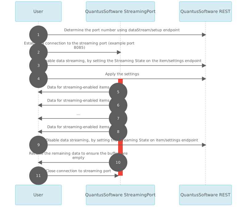
The data stream is framed into packets. A packet can contain info or data for one or multiple channels.
A data packet has 4 distinct parts:
Below is a typical flow chart for reading from the data stream:

| Data type | Member name | Description | Size (Bytes) |
|---|---|---|---|
| 64-bit unsigned integer | Sequence Number | The number of the packet, useful to ensure the User receives all packets. Should also be used to determine whether the QuantusSoftware has discarded any data due to buffering. Resets when a measurement is started. | 8 |
| 64-bit floating point (double) | Transmit Timestamp | The timestamp generated when the packet was filled and marked for sending. This can be used in conjunction with the Sequence number to determine if there is missing data. Resets when a measurement is started. This timestamp should not be used to to align data. |
8 |
| 32-bit floating point (float) | Buffer Level | The level of the buffer used on the system, useful to ensure the User is collecting data fast enough. Once this value exceeds 45% the QuantusSoftware will start discarding data to protect the system. | 4 |
| 32-bit unsigned integer | Payload Size | The total size of the payload in bytes | 4 |
| 32-bit unsigned integer | Byte order marker | QuantusSoftware assumes Little Endian; therefore, this value should equate to 0xFFFE. If it does not, the User will need to do endian conversions on the headers, stats and data. | 4 |
| 32-bit unsigned integer | Payload Type | The payload type is used to identify the type of payload being transmitted by QServer. Data: 0 |
4 |
| Data type | Member name | Description | Size (Bytes) |
|---|---|---|---|
| 32-bit signed integer | Channel ID | Unique identifier for the channel | 4 |
| 32-bit signed integer | Sample Type | Unique enumeration for each Channel Type See Expected data types |
4 |
| 32-bit unsigned integer | Channel Type | Analog: 0 Tacho: 1 CAN: 2 GPS: 3 |
4 |
| 32-bit unsigned integer | Channel Data Size | Size of the channel data in bytes | 4 |
| 64-bit unsigned integer | Timestamp/Offset | Timestamp (Analog data): Indicates the elapsed time in nanoseconds from the PTP Master clock’s epoch for the first sample of analog data. If PTP synchronisation is not active, it indicates the elapsed time in nanoseconds from the start of the measurement. Offset (Digital data): Indicates the offset in nanoseconds to be added to each sample for digital channels. |
8 |
The analog channel header content is dependent on the Analog Data Streaming Format set on the controller node. In order to achieve the highest possible data rates, the User can choose to stream the data in a raw format. With this mode active QServer will not do any processing on the data. The User will receive the data as 16-, 24- or 32-bit raw samples, that requires scaling, as opposed to the Processed mode where the data will be sent as 32-bit floating point values, that can be plotted as is.
| Data type | Member name | Description | Size (Bytes) |
|---|---|---|---|
| 32-bit signed integer | Channel Integrity | Enumeration indicating the integrity status of the channel: Not available: -1 Ok: 0 Overload has occurred1: 1 Short circuit: 2 Open circuit: 3 ADC error: 4 |
4 |
| 32-bit signed integer | Level Crossing Occurred | No level crossing detected: 0 Level crossing detected: 1 This field is currently unsupported and will be fully functional in a future version |
4 |
| 32-bit floating point (float) | Level | A value between 0 and 1 that represents the signal level as a percentage of the full-scale level | 4 |
| 32-bit floating point (float) | Min | The minimum value for this block of data | 4 |
| 32-bit floating point (float) | Max | The maximum value for this block of data | 4 |
Notes:
1. Overload has occurred indicates that the channel’s input has been overloaded. This overload does not necessarily happen at the voltage range assigned to the channel. Some combinations of settings have headroom and channels can process signals above the selected range.
| Data type | Member name | Description | Size (Bytes) |
|---|---|---|---|
| 32-bit signed integer | Channel Integrity | Enumeration indicating the integrity status of the channel: Not available: -1 Ok: 0 Overload has occurred1: 1 Short circuit: 2 Open circuit: 3 ADC error: 4 |
4 |
| 32-bit signed integer | Level Crossing Occurred | No level crossing detected: 0 Level crossing detected: 1 This field is currently unsupported and will be fully functional in a future version |
4 |
| 32-bit floating point (float) | Level | A value between 0 and 1 that represents the signal level as a percentage of the full-scale level | 4 |
| 32-bit floating point (float) | Min | The minimum value for this block of data | 4 |
| 32-bit floating point (float) | Max | The maximum value for this block of data | 4 |
| 32-bit floating point (float) | Scaling factor | The scaling factor to be used when converting the raw data into a user-friendly format | 4 |
Notes:
1. Overload has occurred indicates that the channel’s input has been overloaded. This overload does not necessarily happen at the voltage range assigned to the channel. Some combinations of settings have headroom and channels can process signals above the selected range.
| Data type | Member name | Description | Size (Bytes) |
|---|---|---|---|
| 32-bit unsigned integer | Reserved | Reserved for future use | 4 |
| 32-bit unsigned integer | Reserved | Reserved for future use | 4 |
| 32-bit unsigned integer | Reserved | Reserved for future use | 4 |
| 32-bit unsigned integer | Reserved | Reserved for future use | 4 |
| 32-bit unsigned integer | Reserved | Reserved for future use | 4 |
| 32-bit unsigned integer | Reserved | Reserved for future use | 4 |
| Data type | Member name | Description | Size (Bytes) |
|---|---|---|---|
| 64-bit floating point | Timestamp | Timestamp captured by the GPS device in milliseconds when the message was received, a timestamp value is relative to the start of the measurement. | 8 |
| 16-bit unsigned integer | Accuracy estimate | Time Accuracy Estimate in nanoseconds. | 2 |
| 8-bit unsigned integer | Is Leap Seconds Valid | A boolean flag indicating if the leap seconds value is valid. | 1 |
| 8-bit unsigned integer | Leap Seconds | The GPS leap seconds. | 1 |
In order to determine the expected data type one needs to look at the Channel and the Sample type.
| Channel type | Sample type | Data type | Unit | Description |
|---|---|---|---|---|
| Analog | 0 - Voltage (float) 1 - Raw (int) 2 - Raw (int) 3 - Raw (int) |
32-bit floating point (float) 16-bit fixed point (int) 24-bit fixed point (int) 32-bit fixed point (int) |
Volts Volts Volts Volts |
Analog input samples Raw analog input samples Raw analog input samples Raw analog input samples |
| Tacho | 0 - Timestamps (double) | 64-bit floating point (double) | Milliseconds | Timestamps from the start of measurement |
| CAN/CAN FD | 0 - Raw CAN message | Byte | NA | CAN/CAN FD messages of varying size |
| GPS | 0 - Raw NMEA message | Byte | NA | NMEA messages of varying sizes |
| Field | Data type | Description |
|---|---|---|
| Timestamp | 64-bit floating point | Timestamp captured by the CAN device when the message was received, a timestamp value is relative to the start of the measurement. The timestamp is measured in seconds. |
| ID | 32-bit unsigned integer | Unique message identifier |
| Header | 8-bit unsigned integer | |
| Frame Format | 8-bit unsigned integer | Extended or Standard format |
| Frame Type | 8-bit unsigned integer | Data or Remote type |
| Data Field Length | 8-bit unsigned integer | Number of bytes in the data field |
| Data | Array of 8-bit unsigned integers | Variable length data (1 to 64 bytes) |
In order to align the digital data from tacho or CAN/CAN FD channels with the analog channel data, the active sampling rate of the analog channel is required.
From the Generic Channel Header we obtain the timestamp for analog channels and the offset for digital channels. Each sample of the analog channels’ data represent a duration:
\[\begin{align*} duration = \Big(\frac{1}{Sampling Rate (Hz)}\Big) \end{align*}\]
The following image represents the data received from QServer: 
Where:
With PTP disabled, example timestamps for the analog data:
Given the offsets for the digital channels, we add it to the sample timestamp in order to plot:
The data can be aligned and plotted: 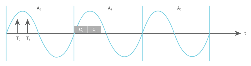
With PTP enabled, the timestamps and offsets will be the time elapsed in nanoseconds since epoch time:
The offsets for the digital channels will be the nanoseconds timestamp when the measurement was started, to plot the samples we need to add the offset to the sample:
Again the data can be aligned and plotted:
Local storage refers to saving the measurement data internally on the device. It can be used in combination with streaming data to a client or on its own. Local storage provides additional data security, by providing redundancy in the case where data is streamed to a connected client as well. Local storage also provides mobility allowing for measurements to be recorded when a streaming client is unavailable.
The following endpoints are available to manage a recording:
| Endpoint | Method | Parameters | Body | Description |
|---|---|---|---|---|
| /localStorage/settings | GET | Returns the local storage settings | ||
| /localStorage/settings | PUT | Updates the local storage settings | ||
| /localstorage/measurement/list | GET | Returns a list containing all measurement names currently stored on local storage | ||
| /recording/startprerun | PUT | Start the pre-run | ||
| /recording/start | PUT | Start the recording | ||
| /recording/stop | PUT | Stop the recording | ||
| /recording/state | GET | Returns the current recording state | ||
| /recording/stats | GET | Returns the current recording stats |
The local storage pre-run stores data in a circular-or ring-buffer, this means that the data for the last X number of seconds, before the recording was started, will be stored to disk. Given a pre-run duration set to 3s and a 5s recording the following images illustrate what will be stored on the disk:

The pre-run buffer will not be filled and only 2s, pre-run data will be stored to disk.

The pre-run buffer will be filled and 3 s pre-run data will be stored to disk.

The pre-run buffer overflows, discarding the first 2s data, storing the last 3s data before the recording was started to disk.
PTP is a protocol for sub-microsecond synchronisation of clocks through a computer network. QuantusSeries devices support PTP Version 2 as defined in the IEEE-1588-2008 standard.
The PTP algorithm defined in the IEEE-1588 standard describes how to adjust the clocks of receiving devices to synchronise to the clock of a transmitting device while compensating for network latency.
A device with a single PTP port is an ordinary clock. Ordinary clocks can be sub-categorised into Master (Primary) and Slave (Secondary) clocks.
Master (Primary) clocks serve as the primary time reference source within a PTP domain. The PTP algorithm automatically ranks PTP clock sources within the domain, and the highest ranking clock source is selected as the Master clock.
Grandmaster clocks are a type of Master clock which receive time information from a source outside of the PTP domain, typically a GNSS satellite source. Grandmaster clocks cannot synchronise to PTP sources to become Slave clocks. Grandmaster clocks are typically ranked the highest by the PTP algorithm (depending on the accuracy of the external time source) and are essential when synchronising to an absolute time reference e.g. International Atomic Time (TAI) or Coordinated Universal Time (UTC).
A QuantusSeries device can assume the role of a Master clock if it is ranked as the best clock source by the PTP algorithm. PTP Slave clocks are synchronised to the internal oscillator of the Master clock of the selected QuantusSeries device.
If the Master clock source of a PTP domain is removed, another ordinary clock within the PTP domain can take over the role of Master clock. QuantusSeries devices which were Slave clocks before the removal of the Master clocks support taking over the role of Master clock.
PTP Slave (Secondary) clocks synchronise to the PTP Master clock source by adjusting their time to match the time of the Master clock.
QuantusSeries devices can be configured to function only as Slave clocks if desired. This can lead to a more deterministic setup free of startup timing constraints.
A transparent clock is an intermediary device between a Master clock and Slave clocks, and is typically a network switch. A transparent clock routes PTP synchronisation messages, but compensates for any internal delays by adjusting the timestamps within the messages. Normal network traffic can also be routed and is not modified by the transparent clock.
A boundary clock is an intermediary device between a Master clock and Slave clocks, and is typically a network switch. A boundary clock terminates the flow of PTP messages received from the Master clock, uses those messages to set its own clock, and then generates new Master clock messages on the ports connected to Slave clocks. Normal network traffic can be routed and is not modified by the boundary clock.
Synchronising QuantusSeries devices using PTP requires the following:
A QuantusSeries device can synchronise with a master clock source with up to 50ns accuracy. The synchronisation accuracy that can be achieved is highly dependent on the configuration of the equipment and the environment.
PTP accuracy depends on the following:
For increased accuracy, network nodes in the synchronisation path should support the IEEE-1588-2008 standard. Network infrastructure that can act as boundary or transparent clock sources is ideal. Such devices compensate for switching delays and result in stable and accurate synchronisation. Infrastructure which prioritises PTP network traffic should yield improved accuracy and stability compared to infrastructure that does not prioritise PTP network traffic.
Increasing the number of network switches between synchronised devices degrades synchronisation accuracy.
High network traffic in the PTP synchronisation path can degrade synchronisation accuracy. Loss of accuracy can become even more pronounced if the network infrastructure is not PTP compliant.
QuantusSeries devices can synchronise accurately over the entire operational range of temperatures. However, sudden temperature changes have a degraded synchronisation accuracy. A QuantusSeries device’s internal temperature should be allowed to stabilise before a high accuracy can be achieved.
The QuantusSeries devices use the following attributes based on the Request-Response Default profile per IEEE 1588-2008 Annex J.3:
| PTP attribute / option | Default value | Configurable |
|---|---|---|
| Best master clock Algorithm | Default per IEEE 1588- 2008 clause 9.3.2 | No |
| Path delay measurement | Delay request-response | No |
| Network transport protocol | UDP/IPv4 | No |
| Transmission mode | Multicast | No |
| One/two step clock | Two step | No |
| defaultDS.domainNumber | 0 | Yes |
| portDS.logAnnounceInterval | 1 | No |
| portDS.logSyncInterval | -3 | No |
| portDS.logMinDelayReqInterval | -3 | No |
| portDS.announceReceiptTimeout | 3 | No |
| defaultDS.priority2 | 128 | No |
| defaultDS.priority2 | 128 | No |
| defaultDS.slaveOnly | 0 | Yes |
PTP synchronisation of the QuantusSeries device can be enabled, disabled and configured using the web interface. Open the web server and navigate to the System Settings, where the PTP synchronisation tab is available.
Configuration options are:
| Configuration option name | Description |
|---|---|
| PTP synchronisation mode |
|
| Domain | The domain number in which the QuantusSeries device operates. A device can only operate in a single domain. Synchronisation messages from different domains are ignored. |
| Accuracy threshold | The maximum synchronisation offset allowed before a QuantusSeries device is considered to no longer be synchronised. PTP synchronisation on a QuantusSeries device is a best effort service, therefore the achievable synchronisation accuracy is network related. A QuantusSeries device will synchronise to the highest achievable accuracy. If the synchronisation offset exceeds the threshold the user will be informed of the event. |
| Synchronisation timeout | The maximum time a QuantusSeries Device is allowed to synchronise to below the accuracy threshold during bootup. If the QuantusSeries Device fails to achieve the specified accuracy in the allowed time, the boot sequence will continue. The PTP status will be “Bad Accuracy” until the offset drops to below the accuracy threshold. |
| Wait for master time | The maximum time a QuantusSeries Device is allowed to search for an existing PTP Master clock source on the network during bootup. If no Master clock was found in the specified time the QuantusSeries Device will become the Master clock. |
| Resynchronisation threshold | The maximum synchronisation offset allowed before complete PTP resynchronisation will be done instead of slow adjustment of the clock. Lower values can significantly improve the synchronisation speed when the synchronisation accuracy has severely degraded, but requires stopping of any active measurements. |
The current PTP state of a QuantusSeries device is displayed on the web interface. The states are:
| PTP State | Description |
|---|---|
| Disabled | PTP synchronisation is disabled. |
| Initialising | The QuantusSeries Device is busy initialising PTP. In this state the QuantusSeries Device starts the Master clock arbitration process and attempts to complete the initial synchronisation to an accuracy below the Accuracy threshold. |
| Master | The QuantusSeries device is the Master clock on the network. |
| Slave | The QuantusSeries device is a Slave clock synchronised to the Master clock. The accuracy is in the acceptable range. |
| Bad accuracy | The synchronisation offset is above the specified Accuracy threshold. |
| Reinitialisation pending | An event occurred that requires PTP synchronisation to reinitialise. The QuantusSeries device will automatically reinitialise PTP as soon as it is safe to do so. The device is determining whether there are measurements currently running on the device. The PTP stack will not change PTP settings during measurements and will wait for the device to be idle. |
| Not synchronised | The device isn’t synchronised. This can happen when the device is set to Slave Only mode and there isn’t a master on the network. |
| Not available | The PTP state has not yet been determined. |
| Initialisation failed | An unexpected error occurred during initialisation. Contact support. |
| Clock configuration option | Minimum | Recommended | Maximum |
|---|---|---|---|
| Announce interval | 2 seconds | 10 seconds | |
| Syncronisation Rate | 4 Hz | 8 Hz | 8 Hz |
| PTP Priority 1 parameter | 128 |
QServer allows streaming of user provided arbitrary waveforms as output signals on supported analog output modules. Setting up the system and channels is done by using the REST API. The data stream that the module outputs is transmitted by the user to QServer on another port.
Two operation modes are available for analog output channels:
Streamed samples should be 4-byte, little-endian single-precision floats between -10 and 10, representing the desired voltage. Decimal values are accepted and rounded to 24-bit resolution. Values outside the voltage range should be avoided.
Configuration endpoints of analog output modules and channels can be found in the Item Settings section of the manual.
Also see Item Settings for a description of the Block Size, Port number and ClearData endpoints.
| Endpoint | Method | Parameters | Return body | Description |
|---|---|---|---|---|
| /alo/startDataStreaming | PUT | Unsigned 64-bit integer representing the output start timestamp in nanoseconds | Simultaneously starts all configured arbitrary waveforms and returns the timestamp at which the signals started. Note that all output modules should have the same sample rate to start at precisely the same time. | |
| /alo/stopDataStreaming | PUT | Stops all arbitrary waveform output channels and clears the buffers. |
Also known as a REST API. A REST (Representation State Transfer) API uses HTTP requests for clients to interact with services. The API adheres to the principles of the REST architecture:

© Mecalc (Pty) Ltd. QuantusSeries and the Q icon are registered trademarks of Mecalc (Pty) Ltd. Information is provided "as is" without warranties or guarantees regarding accuracy, completeness, or suitability for any purpose. Mecalc assumes no liability for its use. Specifications may change without notice.
© Mecalc (Pty) Ltd. QuantusSeries and the Q icon are registered trademarks of Mecalc (Pty) Ltd. Information is provided "as is" without warranties or guarantees regarding accuracy, completeness, or suitability for any purpose. Mecalc assumes no liability for its use. Specifications may change without notice.